- Sign In
- |
- Sign Up
- |
- My Quote (0)
- |
- CART (0)


Keeping Your World Up & Running®

Keeping Your World Up & Running®
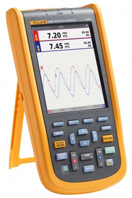
Work with confidence with the oscilloscope that offers simplified testing, more insight, faster electro-mechanical troubleshooting, and comes with 40 MHz of bandwidth. Conveniently measures voltage, current, power waveforms and comes with the Fluke View software.
Work with confidence with the oscilloscope that offers simplified testing, more insight, faster electro-mechanical troubleshooting, and comes with 40 MHz of bandwidth. Conveniently measures voltage, current, power waveforms and comes with the Fluke View software.
Compact and rugged, this oscilloscope is ideal for industrial electrical and electro-mechanical equipment troubleshooting and maintenance applications. Features innovative functions that help technicians troubleshoot faster for quicker results and to keep their systems running smoothly. Additionally, triggering displays waveforms without having to adjust amplitude, timebase, and trigger settings.
Features
Connect-and-View triggering for an instant, stable display
Oscilloscope users know how difficult triggering can be. Using the wrong settings can lead to unstable waveform captures, and sometimes the wrong measurement data. This instrument's unique Connect-andView triggering technology recognizes signal patterns and automatically sets up the correct triggering to provide a stable, reliable, and repeatable display. Connect-and-View triggering is designed to work with virtually any signal, including motor drives and control signals - without adjusting parameters, or even touching a button. Signal changes are instantly recognized and settings are automatically adjusted, providing a stable display even when measuring multiple test points in quick succession.
IntellaSet/AutoReading
The Auto Readings function with Fluke IntellaSet technology uses proprietary algorithms to intelligently analyze the measured waveform and automatically displays the most appropriate numerical measurements on the screen, so you can get the data you need easier than ever before. As an example, when the measured waveform is a line voltage signal, the Vrms and Hz readings are automatically displayed, whereas if the measured waveform is a square wave, the Vpeak-peak, and Hz readings are automatically displayed. Using IntellaSet technology in conjunction with Connect-and-View automatic triggering you can be sure you're seeing not only the correct waveform but the appropriate numerical reading as well. All without touching a button.
Industrial equipment needs a reliable power supply to operate properly, use the dual input to obtain key power measurements
For single-phase or 3-phase balanced systems, the dual inputs of the Industrial ScopeMeter 120B Series can measure AC+DC RMS voltage on channel A and AC+DC RMS current on channel B. This oscilloscope can then calculate; frequency, phase angle, active power (kW), reactive power (VA or var), power factor (PF), or displacement power factor (DPF) and can also calculate the power values for a 3-phase system where all phases have equal voltage and currents. This applies to both balanced systems and resistive loads.
Harmonics Measurement
Harmonics are periodic distortions of voltage, current, or power sine waves. Harmonics in power distribution systems are often caused by non-linear loads such as switched-mode dc power supplies and adjustable speed motor drives. Harmonics can cause transformers, conductors, and motors to overheat. In the Harmonics function, the Test Tool measures harmonics to the 51st. Related data such as dc components, THD (Total Harmonic Distortion), and K factor are measured to provide a complete insight into the electrical state of health of your loads.One test lead to measure multiple electrical parameters
High-frequency waveform, meter, capacitance, and resistance measurements as well as continuity checks are all covered by a single set of shielded test leads. No time is wasted finding or swapping leads.
FlukeView® ScopeMeter Software for Windows
Get more out of your ScopeMeter with FlukeView Software:
Fluke Connect mobile app compatibility
Automated industrial machinery is harder than ever to troubleshoot. It's not enough to just know where you have to test, you also have to know what to look for and that can be hard without baseline measurement data or access to subject matter experts. This Fluke Connect Assets wireless system of software and wireless test tools enables technicians to reduce maintenance costs and increase uptime with accurate equipment records and maintenance data that is easy to interpret, and share. Compare and contrast test point measurement data and trends so you can better understand signal characteristics and changes over time. And, by storing maintenance data on the Fluke Cloud you can enable team members to access it from wherever and whenever they need to so you can get advice or approvals in the field and get your systems up and running faster than ever before.
Use the comprehensive recorder modes to help find intermittent faults with ease
The toughest faults to find are those that happen only once in a while-intermittent event. They can be caused by bad connections, dust, dirt, corrosion, or simply broken wiring or connectors. Other factors, like line outages and sags or the starting and stopping of a motor, can also cause intermittent events resulting in equipment shutdowns. When these events happen, you may not be around to see them. But, your Fluke ScopeMeter Test Tool will. You can either plot the minimum and maximum peak measurement values or record the waveform trace. And, with expandable micro SD memory, recording sessions can be done for up to 14 days. This recorder is even more powerful with the addition of Recorder Event Detect, which makes detecting and logging intermittent faults easier than ever. Just set a threshold on a meter reading or scope trace and deviations are tagged as unique events. You no longer need to search through masses of data to pinpoint faults, and can quickly step from one tagged event to the next, while still having access to the full data set.
Industrial Bus Health Test verifies electrical signal quality on industrial buses
Bus Health Test analyzes the electrical signals on the industrial bus or network and gives a clear "Good", "Weak" or "Bad" indication mark for each of the relevant parameters, presented next to the actual measurement value. Measured values are compared to standard values based on the selected bus types (CAN-bus, Profi-bus, Foundation Field, RS-232, and many more), or, unique reference values can be set if different tolerances are required. This oscilloscope can validate the quality of the electrical signals as soon as they are passed along the network, without looking at the data content. Additionally, this oscilloscope checks the signal levels and speed, transition times and distortion, and compares these to the appropriate standards to help you find errors such as improper cable connections, bad contacts, incorrect grounding, or improper terminators.
Applications
Ideal for industrial electrical and electro-mechanical equipment troubleshooting and maintenance applications
| Oscilloscope Mode (Vertical) | |
| Frequency Response - DC Coupled | Without probes and test leads (with BB120): DC to 40 MHz (-3 dB) With STL120-IV 1:1 shielded test leads: DC to 12.5 MHz (-3 dB), DC to 20 MHz (-6 dB) With VP41 10:1 probe: DC to 40 MHz (-3 dB) |
| Frequency Response - AC Coupled (LF Roll Off) | Without probes and test leads: <10 Hz (-3 dB) With STL120-IV 1:1 shielded test leads: <10 Hz (-3 dB) With VP41 10:1 probe: <10 Hz (-3 dB) |
| Rise Time, Excluding Probes, Test Leads | <8.75 ns |
| Input Impedance | Without probes and test leads: 1 MΩ/20 pF With BB120: 1 MΩ/24 pF With STL120-IV 1:1 shielded test leads: 1 MΩ/230 pF With VP41 10:1 probe: 5 MΩ/15.5 pF |
| Sensitivity | 5 mV to 200 V/div |
| Analog Bandwidth Limiter | 10 kHz |
| Display Modes | A, -A, B, -B |
| Maximum Input Voltage A and B | Direct, with test leads, or with VP41 probe: 600 Vrms CAT IV, 750 Vrms maximum voltage With BB120: 600 Vrms |
| Maximum Floating Voltage, from any Terminal to Ground | 600 Vrms CAT IV, 750 Vrms up to 400 Hz |
| Oscilloscope Mode (Horizontal) | |
| Scope Modes | Normal, single, roll |
| Ranges (Normal) | Equivalent sampling: 10 ns to 500 ns/div Real time sampling: 1 μs to 5 s/div Single (real time): 1 μs to 5 s/div Roll (real time): 1 s to 60 s/div |
| Sampling Rate (for Both Channels Simultaneously) | Equivalent sampling (repetitive signals): up to 4 GS/s Real time sampling 1 μs to 60 s/div: 40 MS/s |
| Trigger | |
| Screen Update | Free run, on trigger |
| Source | A, B |
| Sensitivity A and B | At DC to 5 MHz: 0.5 divisions or 5 mV At 40 MHz: 1.5 divisions At 60 MHz: 4 divisions |
| Slope | Positive, negative |
| Advanced Scope Functions | |
| Display Modes | Normal: Captures up to 25 ns glitches and displays analog-like persistence waveform Smooth: Suppresses noise from a waveform Glitch off: Does not capture glitches between samples Envelope: Records and displays the minimum and maximum of waveforms over time |
| Auto Set (Connect-and-View) | Continuous fully automatic adjustments of amplitude, time base, trigger levels, trigger gap, and hold-off. Manual override by user adjustment of amplitude, time base, or trigger level |
| Input A and B | |
| DC Voltage (V DC) | Ranges: 500 mV, 5, 50, 500, 750 V Accuracy: ±(0.5% +5 counts) Common mode rejection (CMRR): >100 dB at DC, >60 dB at 50, 60, or 400 Hz Full scale reading: 5000 counts |
| True RMS Voltages (V AC and V AC+DC) | Ranges: 500 mV, 5, 50, 500, 750 V Accuracy for 5 to 100% of range (DC coupled) DC to 60 Hz (V AC + DC): ±(1% +10 counts) 1 to 60 Hz (V AC): ±(1% +10 counts) Accuracy for 5 to 100% of range (AC or DC coupled): 60 Hz to 20 kHz: ±(2.5% +15 counts) DC rejection (only V AC): >50 dB Common mode rejection (CMRR): >100 dB at DC; >60 dB at 50, 60, or 400 Hz Full scale reading: 5000 counts, reading is independent of any signal crest factor |
| Peak | Modes: Maximum peak, minimum peak, peak-to-peak Ranges: 500 mV, 5, 50, 500, 2200 V Accuracy: Maximum peak or minimum peak: 5% of full scale; peak-to-peak: 10% of full scale Full scale reading: 500 counts |
| Frequency | Ranges: 1, 10, 100 Hz, 1, 10, 100 kHz, 1, 10, and 70 MHz Frequency range: 15 Hz (1 Hz) to 50 MHz in continuous autoset Accuracy at 1 Hz to 1 MHz: ±(0.5% +2 counts) Full scale reading: 10,000 counts |
| RPM | Maximum reading: 50 kRPM Accuracy: ±(0.5% +2 counts) |
| Duty Cycle | Range: 2 to 98% Frequency range: 15 Hz (1 Hz) to 30 MHz in continuous autoset |
| Pulse Width | Frequency range: 15 Hz (1 Hz) to 30 MHz in continuous autoset Full scale reading: 1000 counts |
| Amperes | With current clamp Ranges: same as V DC, V AC, V AC+DC, or peak Scale factors: 0.1, 1, 10, 100, 400 mV/A, 1 V/A, 10 mV/mA Accuracy: same as V DC, V AC, V AC+DC, or peak (add current clamp uncertainty) |
| Decibel | 0 dBV: 1 V 0 dBm (600/50 Ω): 1 mW referenced to 600 or 50 Ω dB on V DC, V AC, or V AC+DC Full scale reading; 1000 counts |
| Crest Factor | Range: 1 to 10 Full scale reading: 90 counts |
| Phase | Modes: A to B, B to A Range: 0 to 359° Resolution: 1° |
| Power | Configurations: 1 phase/3 phase 3 conductor balanced loads (3 phase: fundamental component only, AUTOSET mode only) Power factor (PF): Ratio between watts and VA range - 0.00 to 1.00 Watt: RMS reading of multiplying corresponding samples of input A (volts) and input B (amperes); Full scale reading: 999 counts VA: Vrms x Arms; Full scale reading: 999 counts VA reactive (var): √((VA)2-W2); Full scale reading: 999 counts |
| Vpwm | Purpose: To measure on pulse width modulated signals, like motor drive inverter outputs Principle: Readings show the effective voltage based on the average value of samples over a whole number of periods of the fundamental frequency Accuracy: As Vrms for sine wave signals |
| Input A to Common | |
| Ohm | Ranges: 50, 500 Ω, 5, 50, 500 kΩ, 5, 30 MΩ Accuracy: ±(0.6% +5 counts) 50 Ω ±(2% +20 counts) Full scale reading: 50 Ω to 5 MΩ - 5000 counts; 30 MΩ - 3000 counts Measurement current: 0.5 mA to 50 nA, decreases with increasing ranges Open circuit voltage: <4 V |
| Common Continuity (Cont) | Beep: <(30 Ω ±5 Ω) in 50 Ω range Measurement current: 0.5 mA Detection of shorts of: ≥1 ms |
| Common Diode | Measurement voltage: At 0.5 mA: >2.8 V At open circuit: <4 V Measurement current: 0.5 mA Polarity: + on input A, - on COM |
| Capacitance (CAP) | Ranges: 50, 500 nF, 5, 50, 500 μF Full scale reading: 5000 counts Measurement current: 500 nA to 0.5 mA, increases with increasing ranges |
| Advanced Meter Functions | |
| Zero Set | Set actual value to reference |
| AutoHold (on A) | Captures and freezes a stable measurement result. Beeps when stable. AutoHold works on the main meter reading, with thresholds of 1 Vpp for AC signals and 100 mV for DC signals |
| Fixed Decimal Point | Activated by using attenuation keys |
| Cursor Readout | |
| Sources | A, B |
| Single Vertical Line | Average, minimum and maximum readout Average, minimum, maximum and time from start of readout (in ROLL mode; instrument in HOLD) Minimum, maximum and time from start of readout (in RECORDER mode; instrument in HOLD) Harmonics values in POWER QUALITY mode |
| Dual Vertical Lines | Peak-peak, time distance and reciprocal time distance readout Average, minimum, maximum and time distance readout (in ROLL mode; instrument in HOLD) |
| Dual Horizontal Lines | High, low and peak-peak readout |
| Rise or Fall Time | Transition time, 0%-level and 100%-level readout (manual or auto leveling; auto leveling only possible in single channel mode) |
| Accuracy | As oscilloscope accuracy |
| Recorder | |
| Meter Readings | Measurement speed: Maximum 2 measurements Record size (minimum, maximum, average): 2 M readings for 1 channel Recorded time span: 2 weeks Maximum number of events: 1024 |
| Waveform Record | Maximum sample rate: 400 K samples Size internal memory: 400 M samples recorded time Span internal memory: 15 minutes at 500 μs/div - 11 hours at 20 ms/div Record size SD card: 1.5 G samples Recorded time span SD card: 11 hours at 500 μs/div - 14 days at 20 ms/div Maximum number of events: 64 |
| Power Quality | |
| Readings | Watt, VA, var, PF, DPF, Hz |
| Watt, VA, Var Ranges (Auto) | 250 W to 250 MW, 625 MW, 1.56 GW When selected: total (%r) ±(2% + 6 counts) When selected: fundamental (%f) ±(4% + 4 counts) |
| DPF | 0.00 to 1.00 |
| PF | 0 to 1, ±0.04 |
| Frequency Range | 10 Hz to 15 kHz 40 to 70 Hz |
| Number of Harmonics | DC to 51 |
| Readings/Cursor Readings (Fundamental 40 to 70 Hz) |
Vrms/Arms /Watt Each harmonic from fundamental maybe selected for individual readings |
| Bus Health Tester | |
| AS-i | Subtype: NEN-EN50295 |
| CAN | Subtype: ISO-11898 |
| Interbus S | Subtype: RS-422 Protocol: EIA-422 |
| Modbus | Subtype: RS-232; Protocol: RS-232/EIA-232 Subtype: RS-485; Protocol: RS-485/EIA-485 |
| Foundation Fieldbus | Subtype: H1 Protocol: 61158 type 1, 31.25 kBit |
| Profibus | Subtype: DP; Protocol: EIA-485 Subtype: PA; Protocol: 61158 type 1 |
| RS-232 | Subtype: EIA-232 |
| RS-485 | Subtype: EIA-485 |
| General Specifications | |
| Waveform Display | Vertical: 10 div of 40 pixels Horizontal: 12 div of 40 pixels |
| Maximum Input Voltage A and B | Direct on input or with leads: 600 Vrms CAT IV for derating With banana-to BNC adapter BB120: 600 Vrms for derating Maximum floating voltage from any terminal to ground: 600 Vrms CAT IV, 750 Vrms up to 400 Hz |
| Display | Type: 5.7" color active martrix TFT Resolution: 640 x 480 |
| Interface | Optically isolated: Transfer screen copies (bitmaps), settings and data USB to PC/laptop: OC4USB optically isolated USB adapter/cable, (optional), using FlukeView® software for Windows® |
| Wireless Radio with Adapter | Frequency range: 2412 to 2462 MHz Output power: <100 mW |
| Environmental | MIL-PRF-28800F, Class 2 |
| Temperature | Battery operation: 32 to 104°F (0 to 40°C) Power adapter operation: 32 to 122°F (0 to 50°C) Storage: -4 to 140°F (-20 to 60°C) non-condensing |
| Humidity (Operating) | At 32 to 50°F (0 to 10°C): non-condensing At 50 to 86°F (10 to 30°C): 95% At 86 to 104°F (30 to 40°C): 75% At 104 to 122°F (40 to 50°C): 45% |
| Altitude | Operating at 10,000' (3 km): CAT III 600 V Operating at 6600' (2 km): CAT IV 600 V Storage: 40,000' (12 km) |
| EMC Electromagnetic Compatibility | USA (FCC): 47 CFR 15 subpart B (this product is considered an exempt device per clause 15.103) |
| Enclosure Protection | IP51, ref: EN/IEC60529 |
| Safety | General: IEC 61010-1: Pollution Degree 2 Measurement: IEC 61010-2-033: CAT IV 600 V/CAT III 750 V |
| Memory | Internal memory can store 20 data sets (screen waveform and setup) Micro SD card slot with optional SD card (maximum size of 32 GB) |
| Power | External: Via power adapter BC430 Input voltage: 10 to 21 V DC Consumption: 5 W typical Input connector: 5 mm jack Internal: Via battery pack BP290 Battery power: Rechargeable Li-Ion 10.8 V Operating time: 7 hours with 50 % backlight brightness Charging time: 4 hours with test tool off, 7 hours with test tool on Allowable ambient temperature: 32 to 104°F (0 to 40°C) during charging |
| Dimensions | 10.2 x 5.2 x 2.15" (259 x 132 x 55 mm) |
| Weight | 3.2 lbs (1.4 kg) including battery pack |

Fluke engineers have delivered an innovative mobile platform and tool that helps solve everyday problems, allowing you to instantly document measurements, retrieve historical data, and share live measurements with your team. All handled by the Android™ or iOS smart phone you already carry.
Fluke Connect with ShareLive™ video call is the only wireless measurement system that lets you stay in contact with your entire team without leaving the field. The Fluke Connect mobile app is works with over 20 different Fluke products - the largest suite of connected test tools in the world.
Make the best decisions faster than ever before by viewing temperature, mechanical, electrical and vibration measurements for each equipment asset in one place. Get started saving time and increasing your productivity.
Click on a category to view a selection of compatible accessories with the Fluke 125B/S Industrial ScopeMeter Hand-Held Oscilloscope with AC clamp and Fluke View software, 40 MHz.


| Oscilloscope Mode (Vertical) | |
| Frequency Response - DC Coupled | Without probes and test leads (with BB120): DC to 40 MHz (-3 dB) With STL120-IV 1:1 shielded test leads: DC to 12.5 MHz (-3 dB), DC to 20 MHz (-6 dB) With VP41 10:1 probe: DC to 40 MHz (-3 dB) |
| Frequency Response - AC Coupled (LF Roll Off) | Without probes and test leads: <10 Hz (-3 dB) With STL120-IV 1:1 shielded test leads: <10 Hz (-3 dB) With VP41 10:1 probe: <10 Hz (-3 dB) |
| Rise Time, Excluding Probes, Test Leads | <8.75 ns |
| Input Impedance | Without probes and test leads: 1 MΩ/20 pF With BB120: 1 MΩ/24 pF With STL120-IV 1:1 shielded test leads: 1 MΩ/230 pF With VP41 10:1 probe: 5 MΩ/15.5 pF |
| Sensitivity | 5 mV to 200 V/div |
| Analog Bandwidth Limiter | 10 kHz |
| Display Modes | A, -A, B, -B |
| Maximum Input Voltage A and B | Direct, with test leads, or with VP41 probe: 600 Vrms CAT IV, 750 Vrms maximum voltage With BB120: 600 Vrms |
| Maximum Floating Voltage, from any Terminal to Ground | 600 Vrms CAT IV, 750 Vrms up to 400 Hz |
| Oscilloscope Mode (Horizontal) | |
| Scope Modes | Normal, single, roll |
| Ranges (Normal) | Equivalent sampling: 10 ns to 500 ns/div Real time sampling: 1 μs to 5 s/div Single (real time): 1 μs to 5 s/div Roll (real time): 1 s to 60 s/div |
| Sampling Rate (for Both Channels Simultaneously) | Equivalent sampling (repetitive signals): up to 4 GS/s Real time sampling 1 μs to 60 s/div: 40 MS/s |
| Trigger | |
| Screen Update | Free run, on trigger |
| Source | A, B |
| Sensitivity A and B | At DC to 5 MHz: 0.5 divisions or 5 mV At 40 MHz: 1.5 divisions At 60 MHz: 4 divisions |
| Slope | Positive, negative |
| Advanced Scope Functions | |
| Display Modes | Normal: Captures up to 25 ns glitches and displays analog-like persistence waveform Smooth: Suppresses noise from a waveform Glitch off: Does not capture glitches between samples Envelope: Records and displays the minimum and maximum of waveforms over time |
| Auto Set (Connect-and-View) | Continuous fully automatic adjustments of amplitude, time base, trigger levels, trigger gap, and hold-off. Manual override by user adjustment of amplitude, time base, or trigger level |
| Input A and B | |
| DC Voltage (V DC) | Ranges: 500 mV, 5, 50, 500, 750 V Accuracy: ±(0.5% +5 counts) Common mode rejection (CMRR): >100 dB at DC, >60 dB at 50, 60, or 400 Hz Full scale reading: 5000 counts |
| True RMS Voltages (V AC and V AC+DC) | Ranges: 500 mV, 5, 50, 500, 750 V Accuracy for 5 to 100% of range (DC coupled) DC to 60 Hz (V AC + DC): ±(1% +10 counts) 1 to 60 Hz (V AC): ±(1% +10 counts) Accuracy for 5 to 100% of range (AC or DC coupled): 60 Hz to 20 kHz: ±(2.5% +15 counts) DC rejection (only V AC): >50 dB Common mode rejection (CMRR): >100 dB at DC; >60 dB at 50, 60, or 400 Hz Full scale reading: 5000 counts, reading is independent of any signal crest factor |
| Peak | Modes: Maximum peak, minimum peak, peak-to-peak Ranges: 500 mV, 5, 50, 500, 2200 V Accuracy: Maximum peak or minimum peak: 5% of full scale; peak-to-peak: 10% of full scale Full scale reading: 500 counts |
| Frequency | Ranges: 1, 10, 100 Hz, 1, 10, 100 kHz, 1, 10, and 70 MHz Frequency range: 15 Hz (1 Hz) to 50 MHz in continuous autoset Accuracy at 1 Hz to 1 MHz: ±(0.5% +2 counts) Full scale reading: 10,000 counts |
| RPM | Maximum reading: 50 kRPM Accuracy: ±(0.5% +2 counts) |
| Duty Cycle | Range: 2 to 98% Frequency range: 15 Hz (1 Hz) to 30 MHz in continuous autoset |
| Pulse Width | Frequency range: 15 Hz (1 Hz) to 30 MHz in continuous autoset Full scale reading: 1000 counts |
| Amperes | With current clamp Ranges: same as V DC, V AC, V AC+DC, or peak Scale factors: 0.1, 1, 10, 100, 400 mV/A, 1 V/A, 10 mV/mA Accuracy: same as V DC, V AC, V AC+DC, or peak (add current clamp uncertainty) |
| Decibel | 0 dBV: 1 V 0 dBm (600/50 Ω): 1 mW referenced to 600 or 50 Ω dB on V DC, V AC, or V AC+DC Full scale reading; 1000 counts |
| Crest Factor | Range: 1 to 10 Full scale reading: 90 counts |
| Phase | Modes: A to B, B to A Range: 0 to 359° Resolution: 1° |
| Power | Configurations: 1 phase/3 phase 3 conductor balanced loads (3 phase: fundamental component only, AUTOSET mode only) Power factor (PF): Ratio between watts and VA range - 0.00 to 1.00 Watt: RMS reading of multiplying corresponding samples of input A (volts) and input B (amperes); Full scale reading: 999 counts VA: Vrms x Arms; Full scale reading: 999 counts VA reactive (var): √((VA)2-W2); Full scale reading: 999 counts |
| Vpwm | Purpose: To measure on pulse width modulated signals, like motor drive inverter outputs Principle: Readings show the effective voltage based on the average value of samples over a whole number of periods of the fundamental frequency Accuracy: As Vrms for sine wave signals |
| Input A to Common | |
| Ohm | Ranges: 50, 500 Ω, 5, 50, 500 kΩ, 5, 30 MΩ Accuracy: ±(0.6% +5 counts) 50 Ω ±(2% +20 counts) Full scale reading: 50 Ω to 5 MΩ - 5000 counts; 30 MΩ - 3000 counts Measurement current: 0.5 mA to 50 nA, decreases with increasing ranges Open circuit voltage: <4 V |
| Common Continuity (Cont) | Beep: <(30 Ω ±5 Ω) in 50 Ω range Measurement current: 0.5 mA Detection of shorts of: ≥1 ms |
| Common Diode | Measurement voltage: At 0.5 mA: >2.8 V At open circuit: <4 V Measurement current: 0.5 mA Polarity: + on input A, - on COM |
| Capacitance (CAP) | Ranges: 50, 500 nF, 5, 50, 500 μF Full scale reading: 5000 counts Measurement current: 500 nA to 0.5 mA, increases with increasing ranges |
| Advanced Meter Functions | |
| Zero Set | Set actual value to reference |
| AutoHold (on A) | Captures and freezes a stable measurement result. Beeps when stable. AutoHold works on the main meter reading, with thresholds of 1 Vpp for AC signals and 100 mV for DC signals |
| Fixed Decimal Point | Activated by using attenuation keys |
| Cursor Readout | |
| Sources | A, B |
| Single Vertical Line | Average, minimum and maximum readout Average, minimum, maximum and time from start of readout (in ROLL mode; instrument in HOLD) Minimum, maximum and time from start of readout (in RECORDER mode; instrument in HOLD) Harmonics values in POWER QUALITY mode |
| Dual Vertical Lines | Peak-peak, time distance and reciprocal time distance readout Average, minimum, maximum and time distance readout (in ROLL mode; instrument in HOLD) |
| Dual Horizontal Lines | High, low and peak-peak readout |
| Rise or Fall Time | Transition time, 0%-level and 100%-level readout (manual or auto leveling; auto leveling only possible in single channel mode) |
| Accuracy | As oscilloscope accuracy |
| Recorder | |
| Meter Readings | Measurement speed: Maximum 2 measurements Record size (minimum, maximum, average): 2 M readings for 1 channel Recorded time span: 2 weeks Maximum number of events: 1024 |
| Waveform Record | Maximum sample rate: 400 K samples Size internal memory: 400 M samples recorded time Span internal memory: 15 minutes at 500 μs/div - 11 hours at 20 ms/div Record size SD card: 1.5 G samples Recorded time span SD card: 11 hours at 500 μs/div - 14 days at 20 ms/div Maximum number of events: 64 |
| Power Quality | |
| Readings | Watt, VA, var, PF, DPF, Hz |
| Watt, VA, Var Ranges (Auto) | 250 W to 250 MW, 625 MW, 1.56 GW When selected: total (%r) ±(2% + 6 counts) When selected: fundamental (%f) ±(4% + 4 counts) |
| DPF | 0.00 to 1.00 |
| PF | 0 to 1, ±0.04 |
| Frequency Range | 10 Hz to 15 kHz 40 to 70 Hz |
| Number of Harmonics | DC to 51 |
| Readings/Cursor Readings (Fundamental 40 to 70 Hz) |
Vrms/Arms /Watt Each harmonic from fundamental maybe selected for individual readings |
| Bus Health Tester | |
| AS-i | Subtype: NEN-EN50295 |
| CAN | Subtype: ISO-11898 |
| Interbus S | Subtype: RS-422 Protocol: EIA-422 |
| Modbus | Subtype: RS-232; Protocol: RS-232/EIA-232 Subtype: RS-485; Protocol: RS-485/EIA-485 |
| Foundation Fieldbus | Subtype: H1 Protocol: 61158 type 1, 31.25 kBit |
| Profibus | Subtype: DP; Protocol: EIA-485 Subtype: PA; Protocol: 61158 type 1 |
| RS-232 | Subtype: EIA-232 |
| RS-485 | Subtype: EIA-485 |
| General Specifications | |
| Waveform Display | Vertical: 10 div of 40 pixels Horizontal: 12 div of 40 pixels |
| Maximum Input Voltage A and B | Direct on input or with leads: 600 Vrms CAT IV for derating With banana-to BNC adapter BB120: 600 Vrms for derating Maximum floating voltage from any terminal to ground: 600 Vrms CAT IV, 750 Vrms up to 400 Hz |
| Display | Type: 5.7" color active martrix TFT Resolution: 640 x 480 |
| Interface | Optically isolated: Transfer screen copies (bitmaps), settings and data USB to PC/laptop: OC4USB optically isolated USB adapter/cable, (optional), using FlukeView® software for Windows® |
| Wireless Radio with Adapter | Frequency range: 2412 to 2462 MHz Output power: <100 mW |
| Environmental | MIL-PRF-28800F, Class 2 |
| Temperature | Battery operation: 32 to 104°F (0 to 40°C) Power adapter operation: 32 to 122°F (0 to 50°C) Storage: -4 to 140°F (-20 to 60°C) non-condensing |
| Humidity (Operating) | At 32 to 50°F (0 to 10°C): non-condensing At 50 to 86°F (10 to 30°C): 95% At 86 to 104°F (30 to 40°C): 75% At 104 to 122°F (40 to 50°C): 45% |
| Altitude | Operating at 10,000' (3 km): CAT III 600 V Operating at 6600' (2 km): CAT IV 600 V Storage: 40,000' (12 km) |
| EMC Electromagnetic Compatibility | USA (FCC): 47 CFR 15 subpart B (this product is considered an exempt device per clause 15.103) |
| Enclosure Protection | IP51, ref: EN/IEC60529 |
| Safety | General: IEC 61010-1: Pollution Degree 2 Measurement: IEC 61010-2-033: CAT IV 600 V/CAT III 750 V |
| Memory | Internal memory can store 20 data sets (screen waveform and setup) Micro SD card slot with optional SD card (maximum size of 32 GB) |
| Power | External: Via power adapter BC430 Input voltage: 10 to 21 V DC Consumption: 5 W typical Input connector: 5 mm jack Internal: Via battery pack BP290 Battery power: Rechargeable Li-Ion 10.8 V Operating time: 7 hours with 50 % backlight brightness Charging time: 4 hours with test tool off, 7 hours with test tool on Allowable ambient temperature: 32 to 104°F (0 to 40°C) during charging |
| Dimensions | 10.2 x 5.2 x 2.15" (259 x 132 x 55 mm) |
| Weight | 3.2 lbs (1.4 kg) including battery pack |
Fluke engineers have delivered an innovative mobile platform and tool that helps solve everyday problems, allowing you to instantly document measurements, retrieve historical data, and share live measurements with your team. All handled by the Android™ or iOS smart phone you already carry.
Fluke Connect with ShareLive™ video call is the only wireless measurement system that lets you stay in contact with your entire team without leaving the field. The Fluke Connect mobile app is works with over 20 different Fluke products - the largest suite of connected test tools in the world.
Make the best decisions faster than ever before by viewing temperature, mechanical, electrical and vibration measurements for each equipment asset in one place. Get started saving time and increasing your productivity.
Click on a category to view a selection of compatible accessories with the Fluke 125B/S Industrial ScopeMeter Hand-Held Oscilloscope with AC clamp and Fluke View software, 40 MHz.