- Sign In
- |
- Sign Up
- |
- My Quote (0)
- |
- CART (0)


Keeping Your World Up & Running®

Keeping Your World Up & Running®
Efficient and reliable, this comprehensive DMM and clamp kit for solar installation diagnostics and maintenance provides high throughput I-V curve tracing and quick, detailed performance data. In addition, this kit includes a 1500 V curve tracer, an FC solar clamp meter, and a digital multimeter.
Efficient and reliable, this comprehensive DMM and clamp kit for solar installation diagnostics and maintenance provides high throughput I-V curve tracing and quick, detailed performance data. In addition, this kit includes a 1500 V curve tracer, an FC solar clamp meter, and a digital multimeter.
Offering comprehensive data analysis and reporting features with an intuitive interface and portable design that makes it easy to use in both the field and the lab, this high-efficiency curve tracer kit gives technicians the ability to make informed decisions, maximizing the efficiency and reliability of solar installations. Built with durability and reliability in mind and boasting several advanced features - including enhanced precision measurement capabilities - this tracer kit is an essential tool for solar professionals seeking to optimize the performance and longevity of individual PV systems.
An intuitive user interface enables easy navigation and real-time analysis, allowing for immediate identification of potential issues. The solar clamp meter enables precise DC and voltage measurements, facilitating performance testing and troubleshooting solar panels and inverters. Additionally, the digital multimeter provides reliable AC/DC voltage, current, resistance, and capacitance measurements, which are essential for verifying system integrity and diagnosing electrical faults.
From commissioning and routine maintenance to troubleshooting and performance optimization, this toolkit empowers solar professionals, allowing them to ensure the efficiency and reliability of solar installations.
Features
PV module and string testing
This kit is specifically designed for testing and analyzing individual solar photovoltaic (PV) modules. It allows users to assess the performance of PV modules accurately, enabling detailed analysis of factors such as shading, mismatch, degradation, and other performance anomalies.
Real-time troubleshooting
With its advanced features and precision measurement capabilities, this high-efficiency Solmetric PV analyzer facilitates real-time troubleshooting of PV modules. This includes detecting issues such as shading or mismatch, allowing for swift identification and resolution of problems to ensure optimal performance of solar installations.
Comprehensive data analysis
Equipped with comprehensive data analysis and reporting features, this analyzer empowers technicians to make informed decisions. Users can analyze data collected by the tracer to gain insights into the efficiency and reliability of solar installations, aiding in performance optimization and maintenance planning.
Portable field testing
The portable design of this kit makes it suitable for field testing applications. Solar professionals can easily transport the tracer to different locations for on-site testing and analysis of PV modules, enabling quick assessment and diagnosis of issues in real-world settings.
Comprehensive measurement and efficient analysis
With a tablet or laptop (Windows only) as the user interface, perform more tests per hour and display the data in multiple, easy-to-read formats.
Save your measurements by touching your customized array tree at the branch you are measuring. The software automatically calculates the expected I-V curve and displays the performance factor.
Precise measurement capabilities
The solar clamp meter enables precise measurement of DC and voltage, while the digital multimeter provides reliable measurements of AC/DC voltage, current, resistance, and capacitance, essential for verifying system integrity and diagnosing electrical faults.
Empowering solar professionals
From commissioning to routine maintenance and troubleshooting, this toolkit empowers solar professionals to ensure the efficiency and reliability of solar installations with ease, thanks to its intuitive user interface and comprehensive diagnostic capabilities.
Accurate measurement of high efficiency modules up to 30 A
Highly efficient modules (>19% module efficiency) possess high capacitance, posing a challenge for some I-V curve tracers that may not be able to measure them. The PVA-1500HE2 is uniquely designed to measure all string types, even those with high efficiency modules, up to 30 A.
Rapid performance in high temperature environments
This I-V curve tracer operates with a swift sweep-to-sweep delay of nine seconds (at VOC <1350V). This results in the ability to measure 3.5 MW within an hour, even in high-temperature settings where standard curve tracers often fail due to overheating.
The SolSensor™ provides irradiance, module temperature, and array tilt data to the PV model. The model uses this information to predict the I-V curve shape at these operating conditions and to translate the measured curve to standard test conditions. The SolSensor™ clamps to the module frame, automatically orienting the irradiance sensor to the plane-of-array.
Irradiance and temperature accuracy
The spectral response of the silicon photodiode sensor in the SolSensor™ is corrected for the PV technology under test. Special factors are provided for multi- and mono-crystalline cells as well as cadmium telluride (CdTe) and other thin-film technologies. The sensor is temperature-compensated and the angular response of each unit is calibrated for rotation and elevation. As a result, the SolSensor™ is accurate over a broad range of technologies, sky conditions, and sun angles, allowing I-V curve measurements earlier and later in the day.
The SolSensor™ provides two external thermocouple inputs for measuring module backside temperatures. Effective cell temperature can also be calculated directly from the measured I-V curve per IEC 60904-5. The PVA’s SmartTemp™ feature, optionally, blends these two methods for best accuracy.
Wireless connectivity
Wireless interface between user's tablet or laptop (Windows), PVA unit, and SolSensor™.
The PVA and SolSensor™ communicate wirelessly with your PC via WiFi with a line-of-sight wireless range of 328' (100 m). That means no wires underfoot, quick setup, the ability to move around while troubleshooting strings, and flexibility to measure multiple combiner boxes with a single SolSensor™ setup.
Turn PVA data into key insights, visualizations, and customizable reports
Capture data in the field with the PVA Application and validate the results with the Data Analysis Tool (DAT), a Microsoft Excel™-based solution streamlining the analysis of PVA I-V curve data. It presents analysis results in multiple formats. It compiles key PV parameters in a string table, flags non-conforming strings, and delivers a statistical overview of the entire array. Additionally, it visually combines string I-V curves at the combiner box level, offering a clear depiction of consistency and identifying atypical strings. The tool also generates histograms for PV parameters across the string population, and this data can be added to a customizable report exported as a PDF. The Data Analysis Tool (DAT) can be downloaded for free use with any PVA.
Supported languages: English, French, Spanish, German, Italian, Traditional Chinese, Simplified Chinese, and Brazilian Portuguese.
Note: The PVA application and the Data Analysis Tool work best with Microsoft Windows 10 or Windows 11.
Applications
| Maximum Current (Isc) Module Efficiency | <19%: 30 A DC ≥19%: 30 A DC |
| Sweep-to-Sweep Delay (at VOC ≥ 1350 V) | <9 seconds |
| Maximum Number of I-V Sweeps per Hour (at VOC ≥ 1350 V) | 400 sweeps/hr |
| Maximum Megawatts Measured per Hour | 3.5 MW/hr |
| Thermal Capacity - Number of I-V Sweeps Before the PVA Must Cool Down | Unlimited: 77°F (25°C) ambient, 9 or 18 second sweep-to-sweep delay 550: 113°F (45°C) ambient, 18 second sweep-to-sweep delay 330: 113°F (45°C) ambient, 9 second sweep-to-sweep delay |
| SolSensor™ | Irradiance accuracy: ±2% when used to predict the performance of well-characterized poly and monocrystalline PV modules with direct irradiance >600 W/m2 Cell temperature accuracy: ±2°C (not including limits of error or thermocouple) Tilt accuracy: ±2° typical (0 to 45°) Update interval: Typically 3.5 seconds Wireless range: 330' (100 m), open line of sight |
| Voltage Range (VOC) | 20 to 1500 V DC |
| Current | 30 A DC (module efficiency <19%) |
| Accuracy | Voltage: ±(0.5% + 0.25 V) Current: ±(0.5% + 0.04 A) Power: ±(1.7% + 1 W), current ≥3 A, module efficiency <19% |
| I-V Trace Points | 100 or 500 (selectable) |
| I-V Sweep Duration | 0.05 to 2 seconds (typically 0.2 seconds for PV strings) |
| Interface to PC/Tablet | WiFi |
| FW Field Updatable | Yes |
| Operating Temperature (Ambient) | 32 to 113°F (0 to 45°C) |
| Safety and Regulatory | CAT III 1500 V, CE, UKCA, TUV, IEC 62446-1 |
| Battery | Lithium-ion |
| Dimensions | 25 x 20 x 17" (63.5 x 50.8 x 43 cm) |
| Weight | 54.92 lbs (24.9 kg) |
 In the past, motor repair meant dealing with traditional three-phase motor failures that were largely the result of water, dust, grease, failed bearings, misaligned motor shafts, or just plain old age. But motor repair has changed in a big way with the introduction of electronically controlled motors, more commonly referred to as adjustable speed drives (ASDs). These drives present a unique set of measurement problems that can vex the most seasoned pro. Thanks to new technology, now for the first time you can take accurate electrical measurements with a DMM during the installation and maintenance of a drive and diagnose bad components and other conditions that may lead to premature failure.

Technicians use many different methods to troubleshoot an electrical circuit, and a good troubleshooter will always find the problem - eventually. The trick is tracking it down quickly and keeping downtime to a minimum. The most efficient troubleshooting procedure begins at the motor and then works systematically back to the electrical source, looking for the most obvious problems first. A lot of time and money can be wasted replacing perfectly good parts when the problem is simply a loose connection. As you go, take care to take accurate measurements. Nobody takes inaccurate measurements on purpose, but it's easy to do, especially when working in a high-energy, noisy environment like an ASD. Likewise, choosing the right test tools for troubleshooting the drive, the motor, and the connections are of utmost importance. This is especially true when taking voltage, frequency, and current measurements on the output side of the motor drive. But until now, there hasn't been a digital multimeter on the market able to accurately measure ASDs. Incorporates a selectable low pass filter* that allows for accurate drive output measurements that agree with the motor drive controller display indicator. Now, technicians won't have to guess whether the drive is operating correctly and delivering the correct voltage, current, or frequency for a given control setting.
Input side measurements
Any good quality True RMS multimeter can verify proper input power to an ASD. The input voltage readings should be within 1% of one another when measured from phase to phase with no load. A significant unbalance may lead to erratic drive operation and should be corrected when discovered.

Output side measurements
On the flip side, a regular True RMS multimeter can't reliably read the output side of a pulse width modulated (PWM) motor drive, because the ASD applies pulse width modulated nonsinusoidal voltage to the motor terminals. A True RMS DMM reads the heating effect of the non-sinusoidal voltage applied to the motor, while the motor controller's output voltage reading only displays the RMS value of the fundamental component (typically from 30 Hz to 60 Hz). The causes of this discrepancy are bandwidth and shielding. Many of today's True RMS digital multimeters have bandwidths out to 20 kHz or more, causing them to respond not only to the fundamental component, which is what the motor responds to but to all of the high-frequency components generated by the PWM drive. And if the DMM isn't shielded for high-frequency noise, the drive controller's high noise levels make the measurement discrepancies even more extreme. With the bandwidth and shielding issues combined, many True RMS meters display readings as much as 20 to 30% higher than what the drive controller is indicating. The incorporated selectable low pass filter allows troubleshooters to take accurate voltage, current, and frequency measurements on the output side of the drive at either the drive itself or the motor terminals. With the filter selected, the readings for both voltage and frequency (motor speed) should agree with the associated drive control display indications, if available. The low pass filter also allows for accurate current measurements when used with Hall-effect type clamps. All of these measurements are especially helpful when taking measurements at the motor location when the drive's displays are not in view.
Taking safe measurements
Before taking any electrical measurements, be sure you understand how to take them safely. No test instrument is completely safe if used improperly, and many test instruments are not appropriate for testing adjustable speed drives. Also, make sure to use the appropriate personal protective equipment (PPE) for your specific working environment and measurements. If at all possible, never work alone.


Safety ratings for electrical test equipment
ANSI and the International Electrotechnical Commission (IEC) are the primary independent organizations that define safety standards for test equipment manufacturers. The IEC 61010 second edition standard for test equipment safety states two basic parameters: a voltage rating and a measurement category rating. The voltage rating is the maximum continuous working voltage the instrument is capable of measuring. The category ratings depict the measurement environment expected for a given category. Most three-phase ASD installations would be considered a CAT III measurement environment, with power supplied from either 480V or 600V distribution systems. When using a DMM for measurements on these high-energy systems, make sure it's rated at a minimum for CAT III 600V and preferably for CAT IV 600V/CAT III 1000V. The category rating and voltage limit are typically found on the front panel, at the input terminals. Dual-rated CAT IV 600V and CAT III 1000V. Refer to the ABC's of DMM Safety* from Fluke for additional information on category ratings and taking safe measurements.
Now let's put the multimeter to the test. The measurements in the following procedure are designed to be made on a 480 volt 3 phase drive control at the control panel terminal strips. These procedures would also be valid for lower voltage 3 phase drives powered by either single or 3 phase supply voltages. For these tests, the motor is running at 50 Hz.
Input voltage
To measure the ac voltage supply to the input side of the drive at the drive:
Input current
Measuring the input current generally requires a current clamp accessory. In most cases, either the input current exceeds the maximum current measurable by the current function, or it isn't practical to "break the circuit" to take an in-line series current measurement. Regardless of clamp type, insure that all readings are within 10% of each other for proper balance.
Transformer type clamp (i200, 80i-400, 80i-600A)
Hall Effect type (AC/DC) clamp (i410,i-1010)
Figure 1. Output voltage reading without using the low pass filter.

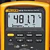
Figure 2. Output voltage reading with low pass filter enabled.
Output voltage
To measure the AC output voltage at either the drive or the motor terminals:
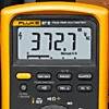
Figure 3. Output frequency (motor speed) without the low pass filter.


Figure 4. Output frequency (motor speed) using the low pass filter.

Motor speed (Output frequency using voltage as a reference)
To determine motor speed, simply take a frequency measurement while using the low pass filter. The measurement can be made between any two of the phase voltage or motor terminals.
Output current
TAs with input current, measuring the output current generally requires a current clamp accessory. Once again, regardless of clamp type, insure that all readings are within 10% of each other for proper balance.
Transformer type clamp (i200, 80i-400, 80i-600A)
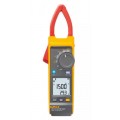
Figure 5. Output current reading without using the low pass filter.


Figure 6. Output current reading with low pass filter enabled.

Hall Effect type (AC/DC) clamp (i410,i-1010)
Motor speed (Output frequency using current as a reference)
For motors that pull at least 20 amps of running current, motor speed can be determined by taking a frequency measurement with current clamps. Until now, noise issues have prevented accurate readings using hall effect type clamps. Here's how the low pass filter makes it possible.
Motor speed using a Hall Effect type (AC/DC) clamp (i410,i-1010)
Motor speed using a transformer type clamp (i200, 80i-400, 80i-600A)
DC Bus measurements
A healthy dc bus is a must for a properly operating motor drive. If the bus voltage is incorrect or unstable, the converter diodes or capacitors may be starting to fail. The DC bus voltage should be approximately 1.414 times the phase to phase input voltage. For a 480 volt input, the DC bus should be approximately 679 VDC. The DC bus is typically labeled as DC+, DC- or B+, Bon the drive terminal strip. To measure the DC bus voltage:
Click on a category to view a selection of compatible accessories with the Fluke SOL-DMM87V-KIT DMM and Clamp Kit.

| Maximum Current (Isc) Module Efficiency | <19%: 30 A DC ≥19%: 30 A DC |
| Sweep-to-Sweep Delay (at VOC ≥ 1350 V) | <9 seconds |
| Maximum Number of I-V Sweeps per Hour (at VOC ≥ 1350 V) | 400 sweeps/hr |
| Maximum Megawatts Measured per Hour | 3.5 MW/hr |
| Thermal Capacity - Number of I-V Sweeps Before the PVA Must Cool Down | Unlimited: 77°F (25°C) ambient, 9 or 18 second sweep-to-sweep delay 550: 113°F (45°C) ambient, 18 second sweep-to-sweep delay 330: 113°F (45°C) ambient, 9 second sweep-to-sweep delay |
| SolSensor™ | Irradiance accuracy: ±2% when used to predict the performance of well-characterized poly and monocrystalline PV modules with direct irradiance >600 W/m2 Cell temperature accuracy: ±2°C (not including limits of error or thermocouple) Tilt accuracy: ±2° typical (0 to 45°) Update interval: Typically 3.5 seconds Wireless range: 330' (100 m), open line of sight |
| Voltage Range (VOC) | 20 to 1500 V DC |
| Current | 30 A DC (module efficiency <19%) |
| Accuracy | Voltage: ±(0.5% + 0.25 V) Current: ±(0.5% + 0.04 A) Power: ±(1.7% + 1 W), current ≥3 A, module efficiency <19% |
| I-V Trace Points | 100 or 500 (selectable) |
| I-V Sweep Duration | 0.05 to 2 seconds (typically 0.2 seconds for PV strings) |
| Interface to PC/Tablet | WiFi |
| FW Field Updatable | Yes |
| Operating Temperature (Ambient) | 32 to 113°F (0 to 45°C) |
| Safety and Regulatory | CAT III 1500 V, CE, UKCA, TUV, IEC 62446-1 |
| Battery | Lithium-ion |
| Dimensions | 25 x 20 x 17" (63.5 x 50.8 x 43 cm) |
| Weight | 54.92 lbs (24.9 kg) |
In the past, motor repair meant dealing with traditional three-phase motor failures that were largely the result of water, dust, grease, failed bearings, misaligned motor shafts, or just plain old age. But motor repair has changed in a big way with the introduction of electronically controlled motors, more commonly referred to as adjustable speed drives (ASDs). These drives present a unique set of measurement problems that can vex the most seasoned pro. Thanks to new technology, now for the first time you can take accurate electrical measurements with a DMM during the installation and maintenance of a drive and diagnose bad components and other conditions that may lead to premature failure.
Technicians use many different methods to troubleshoot an electrical circuit, and a good troubleshooter will always find the problem - eventually. The trick is tracking it down quickly and keeping downtime to a minimum. The most efficient troubleshooting procedure begins at the motor and then works systematically back to the electrical source, looking for the most obvious problems first. A lot of time and money can be wasted replacing perfectly good parts when the problem is simply a loose connection. As you go, take care to take accurate measurements. Nobody takes inaccurate measurements on purpose, but it's easy to do, especially when working in a high-energy, noisy environment like an ASD. Likewise, choosing the right test tools for troubleshooting the drive, the motor, and the connections are of utmost importance. This is especially true when taking voltage, frequency, and current measurements on the output side of the motor drive. But until now, there hasn't been a digital multimeter on the market able to accurately measure ASDs. Incorporates a selectable low pass filter* that allows for accurate drive output measurements that agree with the motor drive controller display indicator. Now, technicians won't have to guess whether the drive is operating correctly and delivering the correct voltage, current, or frequency for a given control setting.
Input side measurements
Any good quality True RMS multimeter can verify proper input power to an ASD. The input voltage readings should be within 1% of one another when measured from phase to phase with no load. A significant unbalance may lead to erratic drive operation and should be corrected when discovered.
Output side measurements
On the flip side, a regular True RMS multimeter can't reliably read the output side of a pulse width modulated (PWM) motor drive, because the ASD applies pulse width modulated nonsinusoidal voltage to the motor terminals. A True RMS DMM reads the heating effect of the non-sinusoidal voltage applied to the motor, while the motor controller's output voltage reading only displays the RMS value of the fundamental component (typically from 30 Hz to 60 Hz). The causes of this discrepancy are bandwidth and shielding. Many of today's True RMS digital multimeters have bandwidths out to 20 kHz or more, causing them to respond not only to the fundamental component, which is what the motor responds to but to all of the high-frequency components generated by the PWM drive. And if the DMM isn't shielded for high-frequency noise, the drive controller's high noise levels make the measurement discrepancies even more extreme. With the bandwidth and shielding issues combined, many True RMS meters display readings as much as 20 to 30% higher than what the drive controller is indicating. The incorporated selectable low pass filter allows troubleshooters to take accurate voltage, current, and frequency measurements on the output side of the drive at either the drive itself or the motor terminals. With the filter selected, the readings for both voltage and frequency (motor speed) should agree with the associated drive control display indications, if available. The low pass filter also allows for accurate current measurements when used with Hall-effect type clamps. All of these measurements are especially helpful when taking measurements at the motor location when the drive's displays are not in view.
Taking safe measurements
Before taking any electrical measurements, be sure you understand how to take them safely. No test instrument is completely safe if used improperly, and many test instruments are not appropriate for testing adjustable speed drives. Also, make sure to use the appropriate personal protective equipment (PPE) for your specific working environment and measurements. If at all possible, never work alone.
Safety ratings for electrical test equipment
ANSI and the International Electrotechnical Commission (IEC) are the primary independent organizations that define safety standards for test equipment manufacturers. The IEC 61010 second edition standard for test equipment safety states two basic parameters: a voltage rating and a measurement category rating. The voltage rating is the maximum continuous working voltage the instrument is capable of measuring. The category ratings depict the measurement environment expected for a given category. Most three-phase ASD installations would be considered a CAT III measurement environment, with power supplied from either 480V or 600V distribution systems. When using a DMM for measurements on these high-energy systems, make sure it's rated at a minimum for CAT III 600V and preferably for CAT IV 600V/CAT III 1000V. The category rating and voltage limit are typically found on the front panel, at the input terminals. Dual-rated CAT IV 600V and CAT III 1000V. Refer to the ABC's of DMM Safety* from Fluke for additional information on category ratings and taking safe measurements.
Now let's put the multimeter to the test. The measurements in the following procedure are designed to be made on a 480 volt 3 phase drive control at the control panel terminal strips. These procedures would also be valid for lower voltage 3 phase drives powered by either single or 3 phase supply voltages. For these tests, the motor is running at 50 Hz.
Input voltage
To measure the ac voltage supply to the input side of the drive at the drive:
Input current
Measuring the input current generally requires a current clamp accessory. In most cases, either the input current exceeds the maximum current measurable by the current function, or it isn't practical to "break the circuit" to take an in-line series current measurement. Regardless of clamp type, insure that all readings are within 10% of each other for proper balance.
Transformer type clamp (i200, 80i-400, 80i-600A)
Hall Effect type (AC/DC) clamp (i410,i-1010)
Figure 1. Output voltage reading without using the low pass filter.
Figure 2. Output voltage reading with low pass filter enabled.
Output voltage
To measure the AC output voltage at either the drive or the motor terminals:
Figure 3. Output frequency (motor speed) without the low pass filter.
Figure 4. Output frequency (motor speed) using the low pass filter.
Motor speed (Output frequency using voltage as a reference)
To determine motor speed, simply take a frequency measurement while using the low pass filter. The measurement can be made between any two of the phase voltage or motor terminals.
Output current
TAs with input current, measuring the output current generally requires a current clamp accessory. Once again, regardless of clamp type, insure that all readings are within 10% of each other for proper balance.
Transformer type clamp (i200, 80i-400, 80i-600A)
Figure 5. Output current reading without using the low pass filter.
Figure 6. Output current reading with low pass filter enabled.
Hall Effect type (AC/DC) clamp (i410,i-1010)
Motor speed (Output frequency using current as a reference)
For motors that pull at least 20 amps of running current, motor speed can be determined by taking a frequency measurement with current clamps. Until now, noise issues have prevented accurate readings using hall effect type clamps. Here's how the low pass filter makes it possible.
Motor speed using a Hall Effect type (AC/DC) clamp (i410,i-1010)
Motor speed using a transformer type clamp (i200, 80i-400, 80i-600A)
DC Bus measurements
A healthy dc bus is a must for a properly operating motor drive. If the bus voltage is incorrect or unstable, the converter diodes or capacitors may be starting to fail. The DC bus voltage should be approximately 1.414 times the phase to phase input voltage. For a 480 volt input, the DC bus should be approximately 679 VDC. The DC bus is typically labeled as DC+, DC- or B+, Bon the drive terminal strip. To measure the DC bus voltage:
Click on a category to view a selection of compatible accessories with the Fluke SOL-DMM87V-KIT DMM and Clamp Kit.


