- Sign In
- |
- Sign Up
- |
- My Quote (0)
- |
- CART (0)


Keeping Your World Up & Running®

Keeping Your World Up & Running®
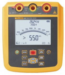
Fast, accurate, and reliable, this advanced insulation tester simplifies frontline troubleshooting, whether working on the factory floor or in the field at a solar installation. In addition, this tester includes both V AC and V DC resistance measurements, a scrollable memory bank and test parameters, and a USB port.
Fast, accurate, and reliable, this advanced insulation tester simplifies frontline troubleshooting, whether working on the factory floor or in the field at a solar installation. In addition, this tester includes both V AC and V DC resistance measurements, a scrollable memory bank and test parameters, and a USB port.
Equipped with an intuitive user interface, a short circuit current of up to 5 mA, and a CAT IV 600 V rating, this portable high-voltage insulation tester delivers rapid and stable resistance measurements no matter where you are. Furthermore, this insulation resistance tester also stores measurements for later review or PC transfer using the provided software.
Features
Safety
The most important reason for testing insulation is to ensure public and personal safety. By performing a high dc voltage test between de-energized current-carrying (hot), grounded, and grounding conductors, you can eliminate the possibility of having a life-threatening short circuit or short to ground which could lead to a fire
Equipment uptime
In addition, insulation testing is important to protect and prolong the life of electrical systems and motors. Periodic maintenance tests can provide valuable information about the state of deterioration and will help in predicting possible failure of the system. Correcting problems will result not only in a trouble-free system, but will also extend the operating life for a variety of equipment
Insulation resistance testers can be used to determine the integrity of windings or cables in motors, transformers, switch-gear, and electrical installations. The test method is determined by the type of equipment being tested and the reason for testing. Spot-reading/short time resistance tests can be used for low-capacitance equipment, while trending tests such as step voltage or dielectric-absorption tests can be used for time-dependent currents that will last for hours.
Insulation regulations
The International Electrical Testing Association (NETA) provides representative and minimum insulation values for various voltage ratings of equipment for use when manufacturer’s data is not available.
Insulation testers are essential in any electrical system for proper and safe equipment operation per industry standards, IEEE Std 43-2000 (Recommended Practice for Testing Insulation Resistance of Rotating Machines), and other recognized organizations.
Insulation resistance basics
Insulation testing is a bit like pressure-checking a plumbing system. You can look for leaks in a plumbing system by forcing water through at a high pressure. The increased pressure makes the leaks easier to spot. The electrical version of pressure is voltage. In insulation testing, we use a relatively high DC voltage to make leakage current more apparent. The instruments are designed to apply the test voltage in a "non-destructive" and very controlled way. Although they supply high voltage, the current they deliver is strictly limited. This helps prevent system damage from failing insulation and keeps the operator from receiving dangerous current levels from accidental contact.
All digital multimeters have a resistance measurement capability (ohms). But this function uses just a few volts. For systems designed to work at more than a few volts, using the standard ohms function does not give us an accurate picture of the insulation integrity. We want to test the insulation at a voltage greater than the working voltage. This will ensure that any leakage will show up and if there is a potential for arcing, we will see it under the controlled test conditions.
Insulation spot test
This can be used to verify the condition of the insulation over the life of a motor by connecting Megohmeter to measure resistance of each winding to ground while recording reading onto graph.
Insulation step voltage
Creates electrical stress on internal insulation cracks to reveal aging or damage not found during other motor insulation tests. This test is done by testing the insulation at two or more voltages and comparing the results.
Polarity index and dielectric absorption ratio
These are timed ratio tests that check the absorption characteristics of wet or contaminated insulation. The PI test is performed over a 10 minute period whereas the DAR ratio test is performed over a 60 second span. There are minimum acceptable polarization index values depending on the insulation class—IEEE Standard 43-2000 covers measurement of polarization index testing:
Applications
| Electrical Specifications | |
| 250 V | Range: <200 kΩ Resolution: Unspecified Accuracy: Unspecified Range: 200 to 500 kΩ Resolution: 1 kΩ Accuracy: 5% Range: 0.5 to 5 mΩ Resolution: 0.01 mΩ Accuracy: 5% Range: 5 to 50 mΩ Resolution: 0.1 mΩ Accuracy: 5% Range: 50 to 500 mΩ Resolution: 1 mΩ Accuracy: 5% Range: 0.5 to 5 gΩ Resolution: 0.01 gΩ Accuracy: 5% Range: 5 to 50 gΩ Resolution: 0.1 gΩ Accuracy: 20% Range: >50 gΩ Resolution: Unspecified Accuracy: Unspecified |
| 500 V | Range: <200 kΩ Resolution: Unspecified Accuracy: Unspecified Range: 200 to 500 kΩ Resolution: 1 kΩ Accuracy: 5% Range: 0.5 to 5 mΩ Resolution: 0.01 mΩ Accuracy: 5% Range: 5 to 50 mΩ Resolution: 0.1 mΩ Accuracy:5% Range: 50 to 500 mΩ Resolution: 1 mΩ Accuracy: 5% Range: 0.5 to 5 gΩ Resolution: 0.01 gΩ Accuracy: 5% Range: 5 to 10 gΩ Resolution: 0.1 gΩ Accuracy: 5% Range: 10 to 50 gΩ Resolution: 0.5 gΩ Accuracy: 20% Range: 50 to 100 gΩ Resolution: 5 gΩ Accuracy: 20% >100 gΩ Resolution: Unspecified Accuracy: Unspecified |
| 1000 V | Range: <200 kΩ Resolution: Unspecified Accuracy: Unspecified Range: 200 to 500 kΩ Resolution: 1 kΩ Accuracy: 5% Range: 0.5 to 5 mΩ Resolution: 0.01 mΩ Accuracy: 5% Range: 5 to 50 mΩ Resolution: 0.1 mΩ Accuracy:5% Range: 50 to 500 mΩ Resolution: 1 mΩ Accuracy: 5% Range: 0.5 to 5 gΩ Resolution: 0.01 gΩ Accuracy: 5% Range: 5 to 20 gΩ Resolution: 0.1 gΩ Accuracy: 5% Range: 20 to 50 gΩ Resolution: 0.5 gΩ Accuracy: 20% Range: 50 to 200 gΩ Resolution: 5 gΩ Accuracy: 20% Range: >200 gΩ Resolution: Unspecified Accuracy: Unspecified |
| 2500 V | Range: <200 kΩ Resolution: Unspecified Accuracy: Unspecified Range: 200 to 500 kΩ Resolution: 1 kΩ Accuracy: 5% Range: 0.5 to 5 mΩ Resolution: 0.01 mΩ Accuracy: 5% Range: 5 to 50 mΩ Resolution: 0.1 mΩ Accuracy:5% Range: 50 to 500 mΩ Resolution: 1 mΩ Accuracy: 5% Range: 0.5 to 5 gΩ Resolution: 0.01 gΩ Accuracy: 5% Range: 5 to 50 gΩ Resolution: 0.1 gΩ Accuracy: 5% Range: 50 to 500 gΩ Resolution: 5 gΩ Accuracy: 20% Range: >500 gΩ Resolution: Unspecified Accuracy: Unspecified |
| Insulation Test Voltage Accuracy | -0%, 10% at 1 mA load current |
| Charging Rate for Capacitive Load | 5 s/µF |
| Leakage Current Measurement | Range: 1 nA to 2 mA Accuracy: ±(20% + 2 nA) |
| Capacitance Measurement | Range: 0.01 µF to 2 µF Accuracy: ±(15% rdg + 0.03 µF) |
| Test Voltage for Insulation Resistance | Range: 250 to 2500 V Accuracy: ±(3% to 3 V) |
| Warning for Energized Circuit | Warning range: >30 V |
| Short Circuit Current | <5 mA |
| Timer | Range: 0 to 99 minutes Indication: 1 second |
| V AC/V DC/Resistance Measurement | |
| V AC | Range: 0 to 600 V Resolution: 0.1 V Accuracy: ±(2% +10), 45 Hz to 500 Hz |
| V DC | Range: 0 to 600 V Resolution: 0.1 V Accuracy: ±(2% +10) |
| Resistance | Range: 0 to 600 Ω 600 to 6000 Ω 6 kΩ to 60 kΩ Resolution: 0.1 Ω 1 Ω 0.01 kΩ Accuracy: ±(2% +10) |
| Safety Specifications | |
| General | IEC 31010-1, pollution degree 2 IEC 61557-1 |
| Measurement | IEC 361010-2-030: CAT IV 600 V IEC 61010-2-034: 2500 V DC |
| Insulation Resistance Measurement | IEC 61557-1 IEC 61557-2 |
| Ingress Protection (IP) Rating | IEC 60529 IP40 |
| General Specifications | |
| Environmental Conditions | Operating temperature: 14 to 122°F (-10 to 50°C) Storage temperature: -4 to 140°F (-20 to 60°C) Operating humidity: Non-condensing (<50°F [10°C]), ≤80% RH (50 to 86°F [10 to 30°C]), ≤50% RH (86 to 122°F [30 to 50°C]) |
| Altitude | Operating altitude: 6562' (2000 m) Storage altitude: 39,370' (12,000 m) |
| Overvoltage Category | CAT IV 600 V |
| International Electromagnetic Compatibility | IEC 61326-1: Portable Electromagnetic Environment IEC 61326-2-2 CISPR 11: Group 1, Class A |
| Display | 3 x 4" (73.5 x 104 mm) |
| Battery | 8 x AA alkaline cells, IEC LR6 |
| Dimensions | 7.2 x 8.3 x 3.7" (184 x 211 x 93 mm) |
| Weight | 2.9 lbs (1.3 kg) |