- Sign In
- |
- Sign Up
- |
- My Quote (0)
- |
- CART (0)


Keeping Your World Up & Running®

Keeping Your World Up & Running®
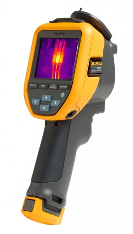
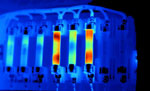
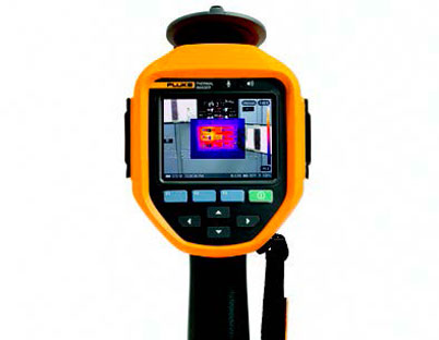
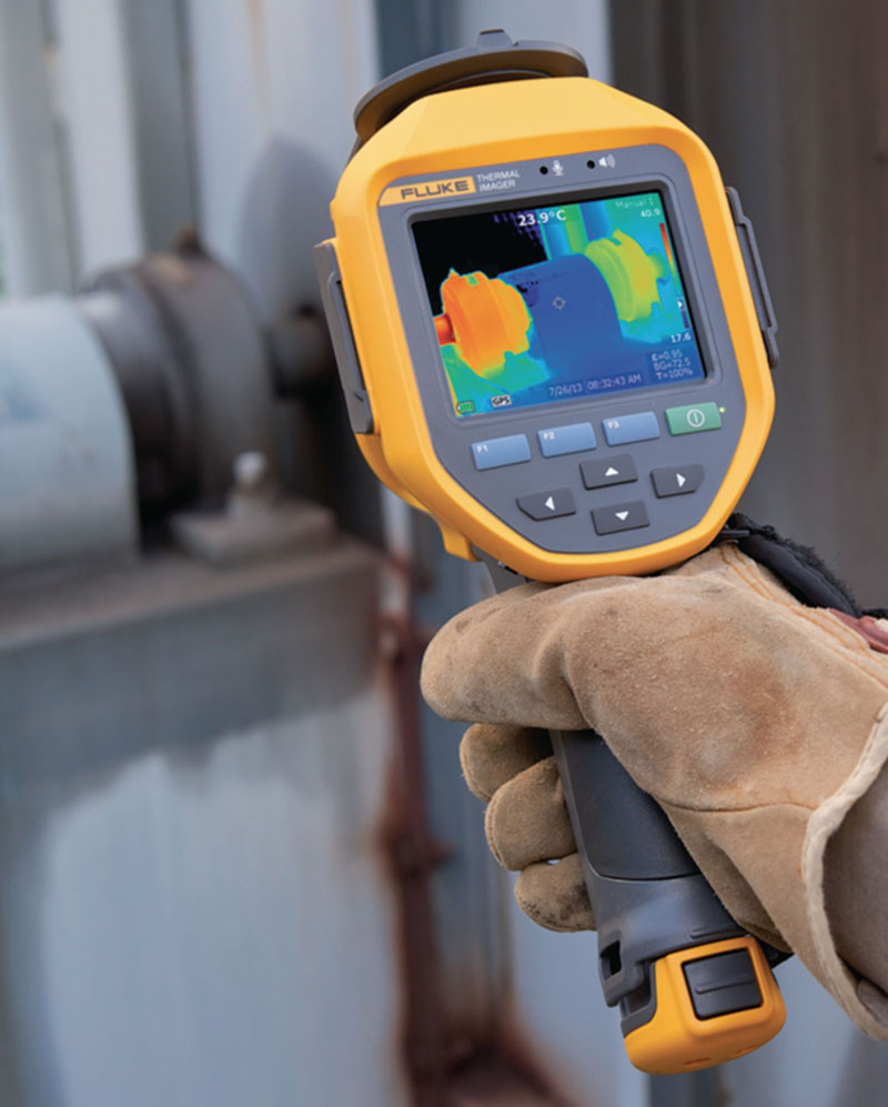
Easy-to-use and built to withstand harsh working conditions, this thermal imager is an ideal tool for electricians, HVAC/R, and maintenance technicians. With an infrared resolution of 120 x 90 (10,800 pixels) and a frame rate of 9 Hz, this camera can measure temperatures ranging between -4 to 302°F (-20 to 150°C).
Easy-to-use and built to withstand harsh working conditions, this thermal imager is an ideal tool for electricians, HVAC/R, and maintenance technicians. With an infrared resolution of 120 x 90 (10,800 pixels) and a frame rate of 9 Hz, this camera can measure temperatures ranging between -4 to 302°F (-20 to 150°C).
Save time with this convenient and reliable thermal imager that provides the right level of infrared and analysis. Work with a rugged imager that can withstand a 2-meter drop, is water/dust resistant, has impressive 5-hour battery life, and makes your job quicker and easier. In addition, with a single touch, IR Fusion technology can pinpoint the location of an issue by combining visible and infrared images for faster inspections and better reporting.
Features
Save time with the right level of infrared and analysis
Whether you are up on the roof inspecting heating, ventilation, and air conditioning, deep in the plant scanning a motor, or if you are locking out an electrical panel, you rely on your tools to have the power and features to get your job done fast.
Get context with a combined visual light and infrared image
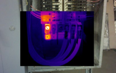
In thermography, context matters. Let Fluke IR-Fusion™ make your job easier by using a thermal image overlaid on a visual light image to give you the full picture of where the issue is before it becomes a problem. Simply slide your finger across the screen to adjust the level of infrared. Whether you are finding an uneven load on switchgear or inspecting a ventilation system, this thermal imaging camera helps you detect issues quickly.
You work hard all day, so should your tools
You cannot afford to have your thermal imager fail due to your environment. You can sleep easy at night knowing that your camera will hold up to whatever the day throws at you.
Longest battery life
This thermal imaging camera can work without a break, with a battery life of over 5 hours of continuous use making it the longest battery life in a Fluke thermal camera ever. Save your battery life in-between inspection points with sleep mode. Simply press the power button one time and you are back up and running.
Stop sorting, start analyzing with Fluke Connect Asset Tagging
Eliminate hours at the computer organizing your thermal images, let Asset Tagging does all that work for you No more dragging and dropping or renaming files in the office, just scan a QR code on your asset, capture your thermal images and they automatically are sorted by asset. Start spending your time analyzing your images and creating reports instead of sorting your files one at a time.
Fluke Connect
Get the most out of your thermal imaging camera with Fluke Connect™ desktop software. Create professional reports in minutes while efficiently capturing full radiometric data to support your maintenance program.
Applications
When conducting infrared inspections, high-quality images that allow for better analysis, presentation, and professionalism are essential.
With a sharply focused image, there is a distinct contrast between areas of varying thermal energy on the surface being inspected. This allows the individual detector elements (also known as pixels) to clearly report the intensity of the energy being focused on them.
When the focus is poor, the incoming energy isn't as concentrated on individual detectors, and their response is skewed. This can lead to temperature measurements that are significantly off, resulting in expensive downtime and possible safety hazards.
Thermal imagers are made with 100% diamond-turned germanium lenses covered with a specialty coating, providing premium quality images.
LaserSharp Auto Focus allows you to select and focus on a specific target
Easily choose and focus on your target
LaserSharp™ Auto Focus uses a built-in laser distance meter that provides both speed and precision. The laser-driven target detection pinpoints the target while the camera focuses to capture a precise, high-quality image. With LaserSharp Auto Focus, you can:
Choose multiple targets at different distances
MultiSharp™ Focus takes multiple images from different focal distances and combines them into one clear image. With a simple point and shoot, you can go from being completely out of focus, to complete focus, throughout the field of view. With MultiSharp:

1.Middleground in focus

2.Foreground in focus

3.Background in focus
Shoot from a distance
Infrared inspections can take you into multiple types of environments with many types of equipment. Interchangeable lenses that require no calibration give you the versatility and the image quality needed to conduct inspections in almost any environment.
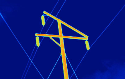
High voltage power pole, captured with a TiX560 camera and standard lens
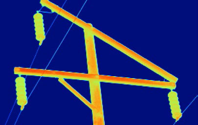
The same power pole captured from the same distance, but with a 2x telephoto lens
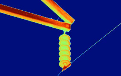
The same power pole captured from the same distance, but with a 4x telephoto lens
Whether you are troubleshooting or conducting maintenance inspections, having easy access to more information faster is always a big benefit.
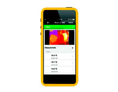

Document information on the equipment you're inspecting
With IR PhotoNotes™, voice or text annotation, you can easily document critical information about each piece of equipment and its location. Each "note" attaches to the image, so you never have to search or match up notes to images.
 |
 |
Image Info | |
| IR Sensor Size | 320 x 240 |
| Distance to Target | 0.69 m |
Main Image Markers | |
| Name | Temperature |
| Centerpoint | 29.1°C |
Capture digital and infrared images at once
IR Fusion™ technology combines visible light and an infrared image into one, giving you better clarity.
IR Fusion picture-in-picture mode: Ironbow palette
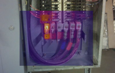
IR Fusion picture-in-picture mode: AutoBlend
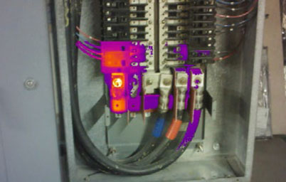
IR Fusion color alarm
Seven benefits of on-site infrared inspections
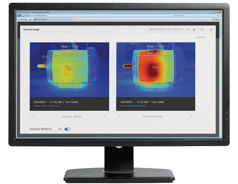
Review thermal images side by side, making it easy to compare today's reading with the baseline or other historical images.
| Key Specifications | |
| Infrared Resolution | 120 x 90 (10,800 pixels) |
| IFOV (Spatial Resolution) | 7.6 mRad, D:S 130:1 |
| Field of View | 50 x 38° |
| Minimum Focus Distance | 20" (50 cm) |
| Focus System | Fixed focus |
| Data Transfer | Mini USB used to transfer image to PC |
| Wireless Connectivity | Yes, (802.11 b/g/n (2.4 GHz)) |
| Fluke Connect Instant Upload | Yes, connect your camera to your building's WiFi network (802.11 b/g/n (2.4 GHz)), and images taken automatically upload to the Fluke Connect system or your local server for storage and viewing on your PC |
| Image Quality | |
| Display | 3.5" LCD touchscreen (landscape) |
| Display Resolution | 320 x 240 LCD |
| Level and Span | Smooth auto and manual scaling |
| IR-Fusion Technology | AutoBlend continuous 0 to 100%. Adds the context of the visible details to your infrared image |
| Thermal Sensitivity (NETD) | 60 mK |
| Frame Rate | 9 Hz |
| Data Storage and Image Capture | |
| Memory | Internal 4GB memory |
| Image Capture, Review, Save Mechanism | One-handed image capture, review, and save capability |
| Image File Formats | Non-radiometric (jpeg), or fully radiometric (.is2); no analysis software required for non-radiometric (jpeg) files |
| Software | Fluke Connect desktop software - full analysis and reporting software with access to the Fluke Connect system |
| Export File Formats with Software | .bmp, .dib, .jpg, .tif, .tiff |
| Temperature Measurement | |
| Temperature Measurement Range (Not Calibrated Below 0°C) |
-4 to 302°F (-20 to 150°C) |
| Accuracy | Target temperature at or over 32°F: Accuracy: ±35.6°C or ±2% at 77°C, whichever is the greater Target temperature at or over 0°C: Accuracy: ±2°C or ±2% at 25°C, whichever is the greater |
| On-Screen Emissivity Correction | Yes, material table |
| On-Screen Reflected Background Temperature Compensation | Yes |
| Center-Point Temperature | Yes |
| Spot Temperature | Hot and cold spot markers |
| Color Palettes | |
| Standard | 6: Ironbow, blue-red, high contrast, amber, hot metal, grayscale |
| General Specifications | |
| Temperature | Operating: 14 to 122°F (-10 to 50°C) Storage: -40 to 158°F (-40 to 70°C) |
| Relative Humidity | 95% non-condensing |
| Infrared Spectral Band | 8 to 14 μm (long wave) |
| Safety | IEC 61010-1: Pollution Degree 2 |
| Electromagnetic Compatibility | EN 61326-1, CISPR 11: Group 1, Class A |
| US FCC | CFR, Part 15C |
| Vibration and Shock | 10 to 150 Hz, 0.15 mm, IEC 60068-2-6; 30 g, 11 ms, IEC 60068-2-27 |
| Drop | Engineered to withstand 6.56' (2 m) drop |
| Battery | Type: Lithium ion smart battery pack with five-segment LED display to show charge level Life: ≥5 hours continuous (without WiFi) Charging time: 2.5 hours to full charge AC operation: AC operation with included power supply (100 to 240 V AC, 50/60 Hz) Power saving: Automatic shutdown: 5, 10, 15 and 20 minutes or never |
| Enclosure Rating | IP54 (protected against dust, limited ingress; protection against water spray from all directions) |
| Supported Languages | Czech, Dutch, English, Finnish, French, German, Hungarian, Italian, Japanese, Korean, Polish, Portuguese, Russian, Simplified Chinese, Spanish, Swedish, Traditional Chinese, and Turkish |
| Dimensions | 10.5 x 4.0 x 5.7" (26.7 x 10.1 x 14.5 cm) |
| Weight | 1.6 lbs (0.72 kg) |
 |
 |
 |
 |
|
| Model | Fluke TiS75+ | Fluke TiS60+ | Fluke TiS55+ | Fluke TiS20+ Fluke TiS20+ MAX |
|---|---|---|---|---|
| Infrared resolution | 384 x 288 (110,592 pixels) | 320 x 240 (76,800 pixels) | 256 x 192 (49,152 pixels) | 120 x 90 (10,800 pixels) |
| IFOV (spatial resolution) | 1.91 mRad | 1.86 mRad | 1.91 mRad | 7.6 mRad |
| Field of view | 42°H x 30°V | 34.1 °H x 25.6°V | 28°H x 20°V | 50°H x 38°V |
| Distance to spot | 130:1 | |||
| Thermal sensitivity* | Target temp at or over 0°C (40 mk) | ≤ 0.045 at 30°C target temp (45 mK) | Target temp at or over 0°C (40 mk) | Target temp at or over 0°C (60 mK) |
| Temperature range | -4 to 1022°F (-20 to 550°C) (not calibrated below -10°C) | -4 to 752°F (-20 to 400°C) | -4 to 1022°F (-20 to 550°C) (not calibrated below -10°C) | TiS20+-4 to +302°F (-20 to 150°C) TiS20+ MAX-4 to +752°F (-20 to 400°C) |
| Focus system | Manual focus plus focus free operation for distances >0.5m via focus marker |
Fixed Focus | Manual focus, plus focus free operation for distances >0.5m via focus marker |
Fixed Focus |
| Level and span | Smooth auto and manual scaling | |||
| Optional lenses | ||||
| Wireless connectivity** | Fluke Connect™ app compatible. Wireless connectivity to PC, iPhone® and iPad® (iOS 4s and later), Android™ 4.3 and up, and WiFi to LAN | |||
| IR-Fusion® | AutoBlend continuous 0 to 100 % | Yes, 4 levels 0%, 25%, 50%, 75%, 100% | AutoBlend continuous 0 to 100 % | Continuous Touchscreen IR-Fusion 0 to 100% |
| Display | 3.5” (8.9 cm landscape) touchscreen 640 x 480 LCD | 3.5” (8.9 cm landscape) 320 x 240 LCD | 3.5” (8.9 cm landscape) touchscreen 640 x 480 LCD | 3.5” (8.9 cm landscape) touchscreen 320 x 240 LCD |
| Design | Pistol-grip design for one-handed use | |||
| Frame rate | 9 or 27 Hz models | < 9 or 30 Hz | 9 or 27 Hz models | 9 Hz |
| Software | Full analysis and reporting software with access to Fluke Connect Desktop | |||
| Voice annotation | Yes, 60 second maximum audio recording via Bluetooth Audio Headset Profile (HSP) connection to external device (sold separately) | 60 seconds maximum recording time per image; reviewable playback on camera; Bluetooth headset required (sold separately) | Yes, 60 second maximum audio recording via Bluetooth Audio Headset Profile (HSP) connection to external device (sold separately) | |
| Text annotation | After IS2 capture, user can type in a note using on-screen keyboard. |
After IS2 capture, user can type in a note using on-screen keyboard. |
Yes. Including standard shortcuts as well as user programmable options | |
| Video recording | Standard and radiometric video. Up to 5 minute recording length. avi and is 3 |
|||
| Battery life | ≥ 3.5 hours continuous without WiFi (Actual life depends on settings and usage) |
4 hours continuous use per battery pack (without WiFi) | ≥ 3.5 hours continuous without WiFi (Actual life depends on settings and usage) |
≥ 5 hours continuous (without WiFi) |
| Remote control operation | ||||
| Alarms | High temperature, low temperature, and dew point calculation | High temperature, low temperature, isotherms (within range) | High temperature, low temperature | |
| Warranty | 2 year warranty | 2 year warranty | 2 year warranty | 2 year warranty |
| Asset tagging | Automatically organize and file thermal images by scanning QR codes | Automatically organize and file thermal images by scanning QR codes | Automatically organize and file thermal images by scanning QR codes | |
*Best possible **Fluke Connect™ not available in all countries

Fluke engineers have delivered an innovative mobile platform and tool that helps solve everyday problems, allowing you to instantly document measurements, retrieve historical data, and share live measurements with your team. All handled by the Android™ or iOS smart phone you already carry.
Fluke Connect with ShareLive™ video call is the only wireless measurement system that lets you stay in contact with your entire team without leaving the field. The Fluke Connect mobile app is works with over 20 different Fluke products - the largest suite of connected test tools in the world.
Make the best decisions faster than ever before by viewing temperature, mechanical, electrical and vibration measurements for each equipment asset in one place. Get started saving time and increasing your productivity.
Whether you choose a simple point-and-shoot model or a high-end thermal imager with all the bells and whistles, here are some key features and specs you should consider:
With a variety of focus mechanisms to choose from, it is important to take into account your skill level as well as the application in selecting a focus type. Here are the common focus mechanisms:
The highest and lowest temperature you encounter in your inspection determines the temperature range you need from your thermal imager. Or, select a camera with a wide temperature range that automatically selects the range based on your scene, or allows you to manually select the temperature range.
A camera that lets you change lenses increases your versatility, allowing you to inspect many more types of equipment and situations. There are lots of choices for lots of applications—standard, wide angle, telephoto, and macro.
Save infrared and digital images and in some cases voice notes to internal memory, a removable SD card, or to a USB flash drive. It’s important to have the flexibility to save images and additional related data to different media for backup or sharing.
Slight differences are easier to see with a monochromatic palette, such as grayscale or amber. High contrast palettes can make it easier to quickly find obvious anomalies. You should be able to change the palette in the camera or in the software.
Use these to quickly highlight areas outside your normal temperature ranges.
Low emissivity surfaces, such as shiny metals, can reflect infrared energy from other objects and throw off your image and your measurement accuracy. So, look for the option to adjust parameters when choosing an imager.
Mark specific temperatures on your image to compare simultaneous temperatures from multiple points on the same image.
Look for a battery with useful features such a charge level indicator. Nothing is worse than starting an inspection with no idea of the battery status. Also consider long battery life and quick charging ability.
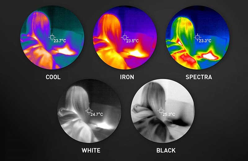
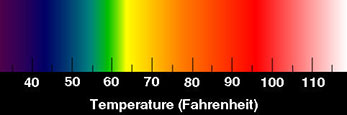
Check out the different color palettes available on your thermal imager!
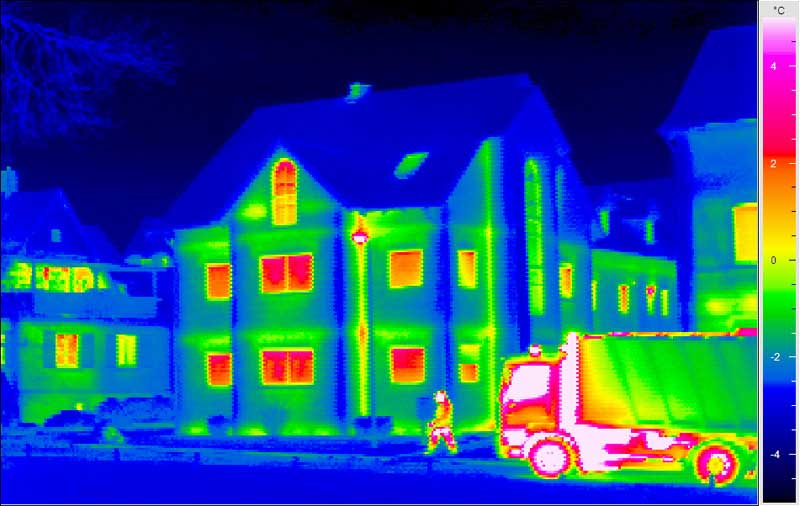
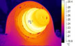
View your home through the eyes of a thermal imager and and see where the hot and cold spots are.
By Sat Sandhu, Fluke
Electronic circuits and components come in a variety of shapes and forms. All electronics operate with current flowing, which in turn leads to power dissipation. This power dissipation manifests itself primarily in the form of heat. Hence a key factor in the design, tests, verification and troubleshooting of all electronics, is heat management. With increasing circuit complexity and or reduction in size, heat management of electronics is taking on a more significant role in the design phase and also in the subsequent phases of test, verification and troubleshooting.
Thermal imaging cameras (TI) are an ideal tool to use in mapping out the heat patterns on electronic circuits and components. Two major advantages of Thermal imaging over contact temperature measurement devices are:
If you would like to learn more about:
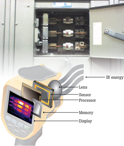
Detailed anatomy of an infrared camera
By Sat Sandhu, Fluke
Infrared cameras, also called thermal imagers, are useful for troubleshooting motor problems as well as for monitoring motor condition for preventative maintenance in power generation, manufacturing and commercial plants. Thermal images of motors reveal their operating condition as indicated by surface temperature. Such condition monitoring is important as a way to avert many unexpected motor malfunctions in systems that are critical to manufacturing.
The onset of motor failures can often be detected by a variety of techniques, including vibration, ultrasound and thermal imaging.
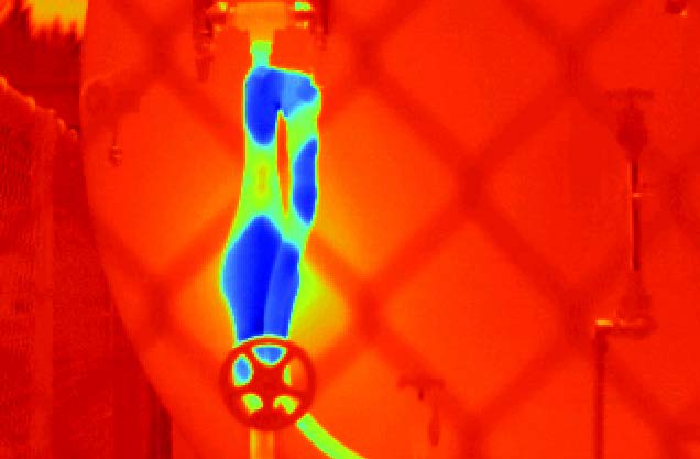
Thermal image of machinery
Why thermal imaging?
Thermal imaging is an effective way to assess equipment condition. Thermal imaging enables you to:
What to scan?
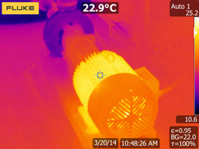
To get started in building heat profiles of your motors, it is a best practice to capture good quality infrared images when the motors are running under normal operating conditions. That gives you baseline measurements of the temperature of components. An infrared camera can capture temperatures of all the critical components: motor, shaft coupling, motor and shaft bearings, and the gearbox.
When you are working with low electrical loads, the indications of a problem may be subtle. Thus a minimum of 40% of design load is recommended (National Fire Protection Association NFPA 70B), and the higher the load, the better. When inspecting in low load situations, be sure to note all possible problems, even if they reflect only a small temperature difference. As a load increases, the temperature will increase too and if a problem exists, expect greater temperature differences at higher loads.
Coupling: This image shows an alignment issue on a motor coupling.
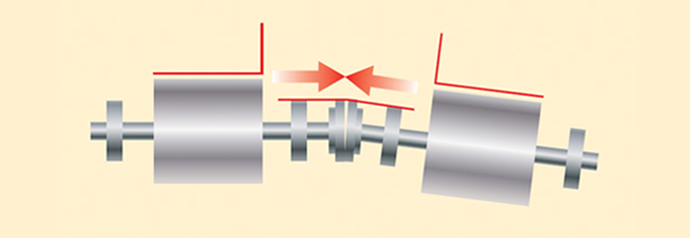
Angular misalignment
The centerline of the two shafts intersect are not parallel.
Combo: This heat pattern indicates an operational motor.
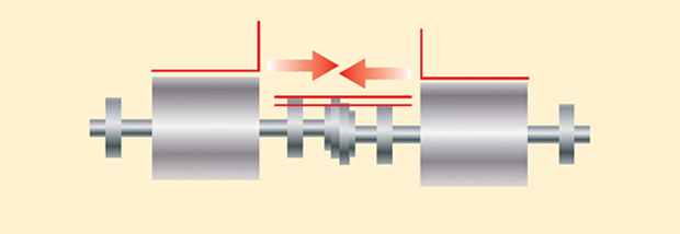
Parallel misalignment
The centerline of the two shafts are parallel but not concentric.
All motors should list the normal operating temperature on the nameplate. Abnormal temperatures, which will show up on a thermal imaging inspection, can be an indication of:
Inadequate cooling because of insufficient air flow. Clearing this issue may only require minor cleaning on the air intake grills.
Power quality issues such as unbalanced voltage or overload or harmonics. All of these will cause excessive heat dissipation.
Impending bearing failure. An overheating bearing is an indication of an impending bearing failure. Bearing condition degrade for a number of reasons:
Insulation failure. With failing insulation of the motor windings the overall motor temperature increases this overheating causes failures and reduces insulation time.
Shaft misalignment. Most misalignment cases are a combination of parallel and angular misalignment (see images above).
Creating regular inspection routes that include thermal images of all critical motor/drive combinations and tracking to those baseline images will help you determine whether a hotspot is unusual or not, and help you verify if the repairs were successful.
Click on a category to view a selection of compatible accessories with the Fluke TiS20+ Thermal Imager, -4 to 302°F.


| Key Specifications | |
| Infrared Resolution | 120 x 90 (10,800 pixels) |
| IFOV (Spatial Resolution) | 7.6 mRad, D:S 130:1 |
| Field of View | 50 x 38° |
| Minimum Focus Distance | 20" (50 cm) |
| Focus System | Fixed focus |
| Data Transfer | Mini USB used to transfer image to PC |
| Wireless Connectivity | Yes, (802.11 b/g/n (2.4 GHz)) |
| Fluke Connect Instant Upload | Yes, connect your camera to your building's WiFi network (802.11 b/g/n (2.4 GHz)), and images taken automatically upload to the Fluke Connect system or your local server for storage and viewing on your PC |
| Image Quality | |
| Display | 3.5" LCD touchscreen (landscape) |
| Display Resolution | 320 x 240 LCD |
| Level and Span | Smooth auto and manual scaling |
| IR-Fusion Technology | AutoBlend continuous 0 to 100%. Adds the context of the visible details to your infrared image |
| Thermal Sensitivity (NETD) | 60 mK |
| Frame Rate | 9 Hz |
| Data Storage and Image Capture | |
| Memory | Internal 4GB memory |
| Image Capture, Review, Save Mechanism | One-handed image capture, review, and save capability |
| Image File Formats | Non-radiometric (jpeg), or fully radiometric (.is2); no analysis software required for non-radiometric (jpeg) files |
| Software | Fluke Connect desktop software - full analysis and reporting software with access to the Fluke Connect system |
| Export File Formats with Software | .bmp, .dib, .jpg, .tif, .tiff |
| Temperature Measurement | |
| Temperature Measurement Range (Not Calibrated Below 0°C) |
-4 to 302°F (-20 to 150°C) |
| Accuracy | Target temperature at or over 32°F: Accuracy: ±35.6°C or ±2% at 77°C, whichever is the greater Target temperature at or over 0°C: Accuracy: ±2°C or ±2% at 25°C, whichever is the greater |
| On-Screen Emissivity Correction | Yes, material table |
| On-Screen Reflected Background Temperature Compensation | Yes |
| Center-Point Temperature | Yes |
| Spot Temperature | Hot and cold spot markers |
| Color Palettes | |
| Standard | 6: Ironbow, blue-red, high contrast, amber, hot metal, grayscale |
| General Specifications | |
| Temperature | Operating: 14 to 122°F (-10 to 50°C) Storage: -40 to 158°F (-40 to 70°C) |
| Relative Humidity | 95% non-condensing |
| Infrared Spectral Band | 8 to 14 μm (long wave) |
| Safety | IEC 61010-1: Pollution Degree 2 |
| Electromagnetic Compatibility | EN 61326-1, CISPR 11: Group 1, Class A |
| US FCC | CFR, Part 15C |
| Vibration and Shock | 10 to 150 Hz, 0.15 mm, IEC 60068-2-6; 30 g, 11 ms, IEC 60068-2-27 |
| Drop | Engineered to withstand 6.56' (2 m) drop |
| Battery | Type: Lithium ion smart battery pack with five-segment LED display to show charge level Life: ≥5 hours continuous (without WiFi) Charging time: 2.5 hours to full charge AC operation: AC operation with included power supply (100 to 240 V AC, 50/60 Hz) Power saving: Automatic shutdown: 5, 10, 15 and 20 minutes or never |
| Enclosure Rating | IP54 (protected against dust, limited ingress; protection against water spray from all directions) |
| Supported Languages | Czech, Dutch, English, Finnish, French, German, Hungarian, Italian, Japanese, Korean, Polish, Portuguese, Russian, Simplified Chinese, Spanish, Swedish, Traditional Chinese, and Turkish |
| Dimensions | 10.5 x 4.0 x 5.7" (26.7 x 10.1 x 14.5 cm) |
| Weight | 1.6 lbs (0.72 kg) |
|
|
|
|
|
|
| Model | Fluke TiS75+ | Fluke TiS60+ | Fluke TiS55+ | Fluke TiS20+ Fluke TiS20+ MAX |
|---|---|---|---|---|
| Infrared resolution | 384 x 288 (110,592 pixels) | 320 x 240 (76,800 pixels) | 256 x 192 (49,152 pixels) | 120 x 90 (10,800 pixels) |
| IFOV (spatial resolution) | 1.91 mRad | 1.86 mRad | 1.91 mRad | 7.6 mRad |
| Field of view | 42°H x 30°V | 34.1 °H x 25.6°V | 28°H x 20°V | 50°H x 38°V |
| Distance to spot | 130:1 | |||
| Thermal sensitivity* | Target temp at or over 0°C (40 mk) | ≤ 0.045 at 30°C target temp (45 mK) | Target temp at or over 0°C (40 mk) | Target temp at or over 0°C (60 mK) |
| Temperature range | -4 to 1022°F (-20 to 550°C) (not calibrated below -10°C) | -4 to 752°F (-20 to 400°C) | -4 to 1022°F (-20 to 550°C) (not calibrated below -10°C) | TiS20+-4 to +302°F (-20 to 150°C) TiS20+ MAX-4 to +752°F (-20 to 400°C) |
| Focus system | Manual focus plus focus free operation for distances >0.5m via focus marker |
Fixed Focus | Manual focus, plus focus free operation for distances >0.5m via focus marker |
Fixed Focus |
| Level and span | Smooth auto and manual scaling | |||
| Optional lenses | ||||
| Wireless connectivity** | Fluke Connect™ app compatible. Wireless connectivity to PC, iPhone® and iPad® (iOS 4s and later), Android™ 4.3 and up, and WiFi to LAN | |||
| IR-Fusion® | AutoBlend continuous 0 to 100 % | Yes, 4 levels 0%, 25%, 50%, 75%, 100% | AutoBlend continuous 0 to 100 % | Continuous Touchscreen IR-Fusion 0 to 100% |
| Display | 3.5” (8.9 cm landscape) touchscreen 640 x 480 LCD | 3.5” (8.9 cm landscape) 320 x 240 LCD | 3.5” (8.9 cm landscape) touchscreen 640 x 480 LCD | 3.5” (8.9 cm landscape) touchscreen 320 x 240 LCD |
| Design | Pistol-grip design for one-handed use | |||
| Frame rate | 9 or 27 Hz models | < 9 or 30 Hz | 9 or 27 Hz models | 9 Hz |
| Software | Full analysis and reporting software with access to Fluke Connect Desktop | |||
| Voice annotation | Yes, 60 second maximum audio recording via Bluetooth Audio Headset Profile (HSP) connection to external device (sold separately) | 60 seconds maximum recording time per image; reviewable playback on camera; Bluetooth headset required (sold separately) | Yes, 60 second maximum audio recording via Bluetooth Audio Headset Profile (HSP) connection to external device (sold separately) | |
| Text annotation | After IS2 capture, user can type in a note using on-screen keyboard. |
After IS2 capture, user can type in a note using on-screen keyboard. |
Yes. Including standard shortcuts as well as user programmable options | |
| Video recording | Standard and radiometric video. Up to 5 minute recording length. avi and is 3 |
|||
| Battery life | ≥ 3.5 hours continuous without WiFi (Actual life depends on settings and usage) |
4 hours continuous use per battery pack (without WiFi) | ≥ 3.5 hours continuous without WiFi (Actual life depends on settings and usage) |
≥ 5 hours continuous (without WiFi) |
| Remote control operation | ||||
| Alarms | High temperature, low temperature, and dew point calculation | High temperature, low temperature, isotherms (within range) | High temperature, low temperature | |
| Warranty | 2 year warranty | 2 year warranty | 2 year warranty | 2 year warranty |
| Asset tagging | Automatically organize and file thermal images by scanning QR codes | Automatically organize and file thermal images by scanning QR codes | Automatically organize and file thermal images by scanning QR codes | |
*Best possible **Fluke Connect™ not available in all countries
Fluke engineers have delivered an innovative mobile platform and tool that helps solve everyday problems, allowing you to instantly document measurements, retrieve historical data, and share live measurements with your team. All handled by the Android™ or iOS smart phone you already carry.
Fluke Connect with ShareLive™ video call is the only wireless measurement system that lets you stay in contact with your entire team without leaving the field. The Fluke Connect mobile app is works with over 20 different Fluke products - the largest suite of connected test tools in the world.
Make the best decisions faster than ever before by viewing temperature, mechanical, electrical and vibration measurements for each equipment asset in one place. Get started saving time and increasing your productivity.
Whether you choose a simple point-and-shoot model or a high-end thermal imager with all the bells and whistles, here are some key features and specs you should consider:
With a variety of focus mechanisms to choose from, it is important to take into account your skill level as well as the application in selecting a focus type. Here are the common focus mechanisms:
The highest and lowest temperature you encounter in your inspection determines the temperature range you need from your thermal imager. Or, select a camera with a wide temperature range that automatically selects the range based on your scene, or allows you to manually select the temperature range.
A camera that lets you change lenses increases your versatility, allowing you to inspect many more types of equipment and situations. There are lots of choices for lots of applications—standard, wide angle, telephoto, and macro.
Save infrared and digital images and in some cases voice notes to internal memory, a removable SD card, or to a USB flash drive. It’s important to have the flexibility to save images and additional related data to different media for backup or sharing.
Slight differences are easier to see with a monochromatic palette, such as grayscale or amber. High contrast palettes can make it easier to quickly find obvious anomalies. You should be able to change the palette in the camera or in the software.
Use these to quickly highlight areas outside your normal temperature ranges.
Low emissivity surfaces, such as shiny metals, can reflect infrared energy from other objects and throw off your image and your measurement accuracy. So, look for the option to adjust parameters when choosing an imager.
Mark specific temperatures on your image to compare simultaneous temperatures from multiple points on the same image.
Look for a battery with useful features such a charge level indicator. Nothing is worse than starting an inspection with no idea of the battery status. Also consider long battery life and quick charging ability.
Check out the different color palettes available on your thermal imager!
View your home through the eyes of a thermal imager and and see where the hot and cold spots are.
By Sat Sandhu, Fluke
Electronic circuits and components come in a variety of shapes and forms. All electronics operate with current flowing, which in turn leads to power dissipation. This power dissipation manifests itself primarily in the form of heat. Hence a key factor in the design, tests, verification and troubleshooting of all electronics, is heat management. With increasing circuit complexity and or reduction in size, heat management of electronics is taking on a more significant role in the design phase and also in the subsequent phases of test, verification and troubleshooting.
Thermal imaging cameras (TI) are an ideal tool to use in mapping out the heat patterns on electronic circuits and components. Two major advantages of Thermal imaging over contact temperature measurement devices are:
If you would like to learn more about:
Detailed anatomy of an infrared camera
By Sat Sandhu, Fluke
Infrared cameras, also called thermal imagers, are useful for troubleshooting motor problems as well as for monitoring motor condition for preventative maintenance in power generation, manufacturing and commercial plants. Thermal images of motors reveal their operating condition as indicated by surface temperature. Such condition monitoring is important as a way to avert many unexpected motor malfunctions in systems that are critical to manufacturing.
The onset of motor failures can often be detected by a variety of techniques, including vibration, ultrasound and thermal imaging.
Thermal image of machinery
Why thermal imaging?
Thermal imaging is an effective way to assess equipment condition. Thermal imaging enables you to:
What to scan?
To get started in building heat profiles of your motors, it is a best practice to capture good quality infrared images when the motors are running under normal operating conditions. That gives you baseline measurements of the temperature of components. An infrared camera can capture temperatures of all the critical components: motor, shaft coupling, motor and shaft bearings, and the gearbox.
When you are working with low electrical loads, the indications of a problem may be subtle. Thus a minimum of 40% of design load is recommended (National Fire Protection Association NFPA 70B), and the higher the load, the better. When inspecting in low load situations, be sure to note all possible problems, even if they reflect only a small temperature difference. As a load increases, the temperature will increase too and if a problem exists, expect greater temperature differences at higher loads.
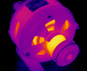
Coupling: This image shows an alignment issue on a motor coupling.
Angular misalignment
The centerline of the two shafts intersect are not parallel.
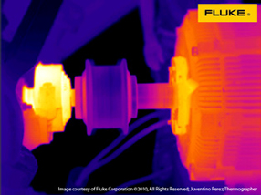
Combo: This heat pattern indicates an operational motor.
Parallel misalignment
The centerline of the two shafts are parallel but not concentric.
All motors should list the normal operating temperature on the nameplate. Abnormal temperatures, which will show up on a thermal imaging inspection, can be an indication of:
Inadequate cooling because of insufficient air flow. Clearing this issue may only require minor cleaning on the air intake grills.
Power quality issues such as unbalanced voltage or overload or harmonics. All of these will cause excessive heat dissipation.
Impending bearing failure. An overheating bearing is an indication of an impending bearing failure. Bearing condition degrade for a number of reasons:
Insulation failure. With failing insulation of the motor windings the overall motor temperature increases this overheating causes failures and reduces insulation time.
Shaft misalignment. Most misalignment cases are a combination of parallel and angular misalignment (see images above).
Creating regular inspection routes that include thermal images of all critical motor/drive combinations and tracking to those baseline images will help you determine whether a hotspot is unusual or not, and help you verify if the repairs were successful.
Click on a category to view a selection of compatible accessories with the Fluke TiS20+ Thermal Imager, -4 to 302°F.